A method for determining the position of a main beam of a wing-body fusion body aircraft

A technology for determining methods and fusion, applied in special data processing applications, instruments, electrical digital data processing, etc., can solve problems such as cumbersome iterative process, long design cycle, low design efficiency, etc., to reduce the iterative process, save costs, The effect of improving design efficiency

Active Publication Date: 2019-05-03
XIAN AIRCRAFT DESIGN INST OF AVIATION IND OF CHINA
View PDF17 Cites 2 Cited by
  • Summary
  • Abstract
  • Description
  • Claims
  • Application Information

AI Technical Summary

Problems solved by technology

[0003] Purpose of the invention: To propose a method for determining the position of the main girder of a wing-body fusion aircraft, so as to solve the problems that the iterative process of structural design and strength verification in the existing method is too cumbersome, the design cycle is long, and the design efficiency is low

Method used


Image

  • A method for determining the position of a main beam of a wing-body fusion body aircraft
  • A method for determining the position of a main beam of a wing-body fusion body aircraft
  • A method for determining the position of a main beam of a wing-body fusion body aircraft

Examples


Embodiment Construction

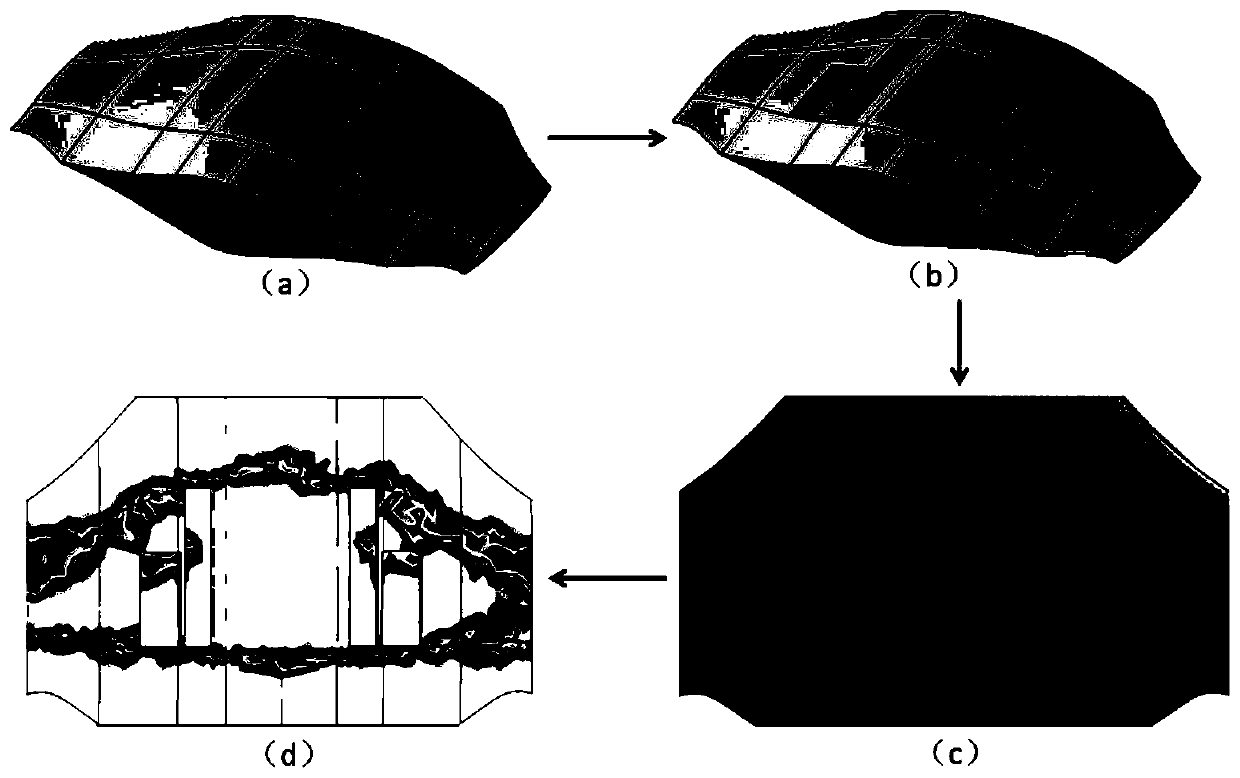
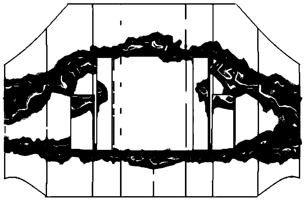
[0011] See attached Figure 1-2 , The invention provides a method for determining the position of the main girder in the fusion area of ​​a wing-body fusion aircraft. by figure 1 The solid structure of the fusion body shown as an example, the steps to determine the position of the main beam are as follows: first step, make the necessary cabin openings on the entity, such as the landing gear compartment and the equipment compartment, to form the wing-body fusion area with openings ,Such as figure 1 (a)-(b); The second step is to carry out finite element solid modeling, set uniform material properties, set boundary conditions, and apply loads, such as figure 1 (c); The third step is to conduct topology optimization analysis, set the minimum structural weight as the optimization goal, and obtain the optimization analysis results, such as figure 1 (d), the darker the color in the figure, the more load transfer; the fourth step is to determine the positions of the front beam and...


PUM


Abstract

The invention belongs to the technical field of aircraft structure design, and particularly relates to a method for determining the position of a wing body fusion body aircraft main beam. The method comprises the following steps: 1) making a necessary cabin body opening on the entity, such as an undercarriage cabin and an equipment cabin, and forming a wing body fusion area with an opening; 2) carrying out finite element entity modeling, setting a unified material attribute, setting a boundary condition, and applying a load; 3) performing topological optimization analysis, and setting the minimum structural weight as an optimization target to obtain an optimization analysis result; and (4) determining the positions of the front beam and the rear beam according to an optimization analysis result. Compared with the traditional structure design, the method has the advantages that the iteration process of the structure design and strength checking can be greatly reduced, the design periodis shortened, the design efficiency is improved, the cost is saved, and the determined position of the main beam is more accurate.

Description

technical field [0001] The invention belongs to the technical field of aircraft structure design, and in particular relates to a method for determining the position of a main girder of a wing-body fusion aircraft. Background technique [0002] The layout position of the main girder of the wing-body fusion aircraft involves the overall force transmission of the aircraft, and its key is self-evident. The existing technology usually determines the position of the main girder from the structure according to the overall shape of the aircraft, and then checks the strength. After many The position of the main girder is determined after rounds of iterations, the process is complicated and inefficient. Contents of the invention [0003] Purpose of the invention: To propose a method for determining the position of the main girder of a wing-body fusion aircraft, so as to solve the problems of the existing method that the iterative process of structural design and strength verificatio...

Claims


Application Information

Patent Timeline
Patent Type & Authority Applications(China)
IPC IPC(8): G06F17/50
CPCY02T90/00
Inventor 李驰郑茂亮
Owner XIAN AIRCRAFT DESIGN INST OF AVIATION IND OF CHINA
Why Eureka
Try Eureka