
Tool setting method for annular mortise machining

A tongue-and-groove and ring technology, applied in the field of tool setting point selection, can solve problems such as unqualified machining dimensions, and achieve the effect of ensuring accuracy

Active Publication Date: 2019-05-07
CHINA HANGFA GUIZHOU LIYANG AVIATION POWER CO LTD
View PDF10 Cites 1 Cited by
  • Summary
  • Abstract
  • Description
  • Claims
  • Application Information

AI Technical Summary

Problems solved by technology

[0005] The technical problem to be solved by the present invention is to provide a tool setting method with multiple tool setting points for the problem of unqualified processing size due to material deformation when processing annular tenon grooves

Method used


Image

  • Tool setting method for annular mortise machining
  • Tool setting method for annular mortise machining
  • Tool setting method for annular mortise machining

Examples


Embodiment

[0021] Embodiment: In this embodiment, the longitudinal direction is the X direction, and the horizontal direction is the Z direction. When setting the knife, it is the edge setting of the knife, that is, Z=0.

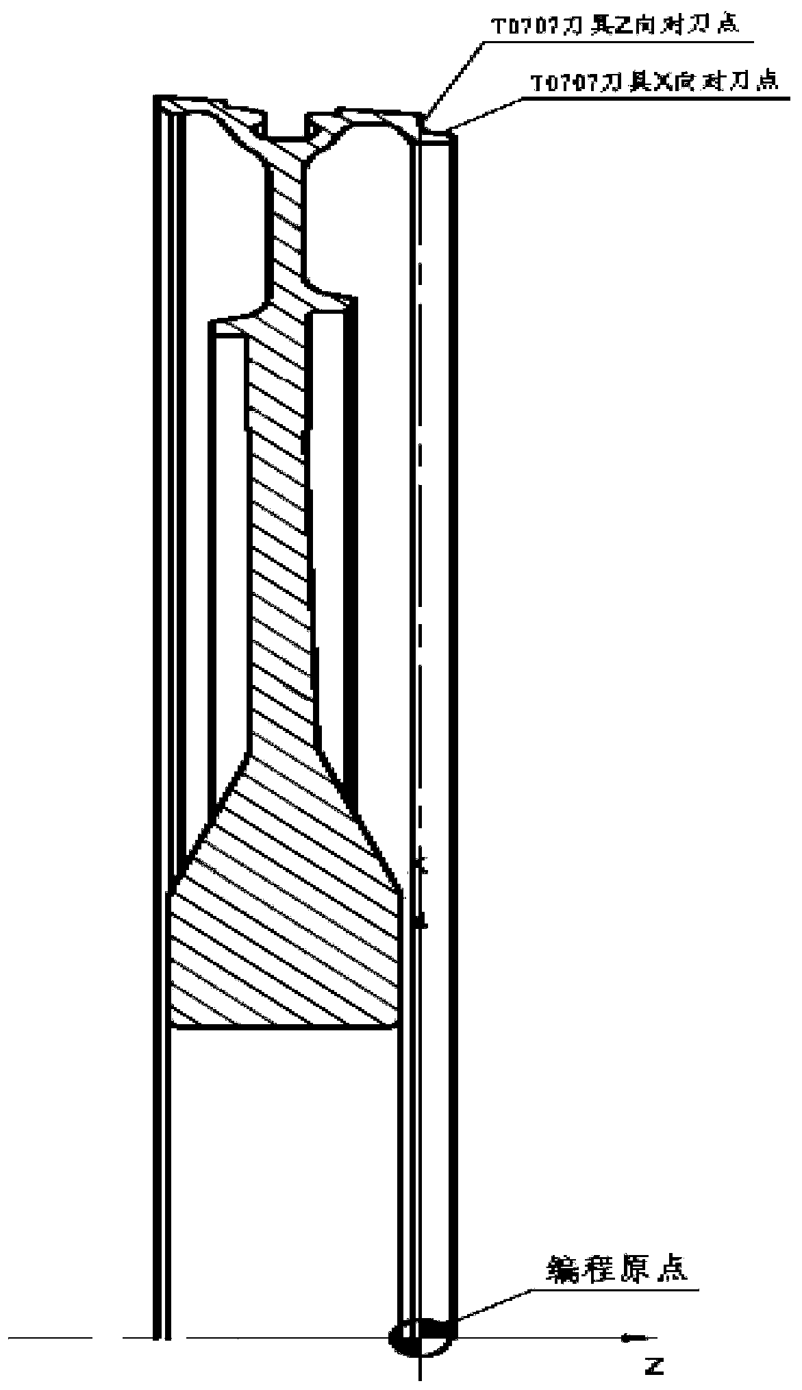
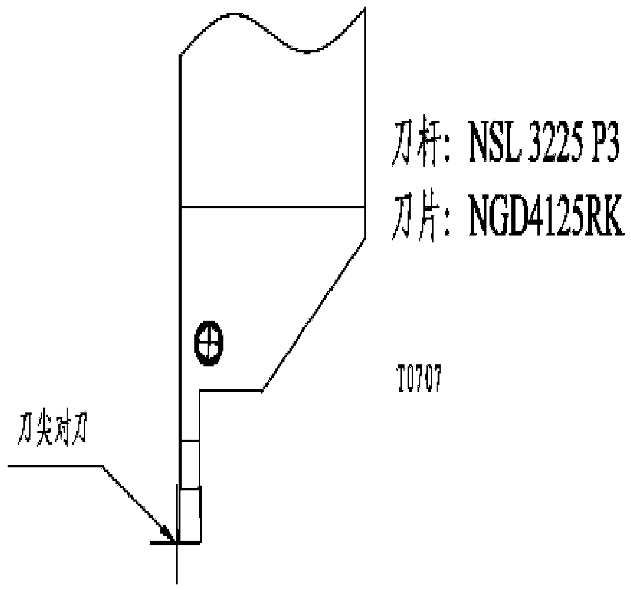
[0022] ①The tool setting point of the first straight tool (No. T0707 tool): X direction tool setting point, figure 1 Shown is straight OD. Z-direction tool setting point: the end face of the reference position of the part, such as figure 1 shown. figure 2 A schematic diagram of the tool. Selection of the first tool setting point: such as figure 1 As shown, because the slotting knife is the initial slotting (that is, ordinary outer circle slotting)

[0023] reason:

[0024] The normal initial grooving accuracy can be guaranteed with the accuracy of the end-to-knife. Therefore, the exposed straight mouth is selected as the X-direction tool-setting point for this tool-setting point, and the end face as shown in the figure is used as the Z-direction tool-setting poi...


PUM


Abstract

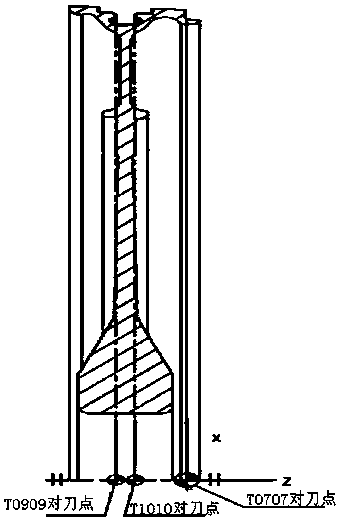
The invention discloses a tool setting method for annular mortise machining. An excircle open groove is formed in the side surface of a part to be machined, and an annular mortise is formed in the longitudinal direction of the middle part; an exposed straight opening of the excircle open groove in the side surface is chosen as a first longitudinal tool setting point at first, and the end surface of the excircle open groove is chosen as a first transversal tool setting point; after the excircle open groove is machined, the right side or the left side of the bottom end surface of the annular mortise is taken as a second longitudinal tool setting point, and the right side surface or the left side surface of the narrowest part of the annular mortise is taken as a second transversal tool setting point; and finally the left side or the right side of the bottom end surface of the annular mortise is taken as a third longitudinal tool setting point, and the left side surface or the right side surface of the narrowest part of the annular mortise is taken as a third transversal tool setting point. The tool setting method is applicable to turning machining for annular mortises in various typesof disc parts of aero-engines, and capable of ensuring the technical requirements of machining accuracy, symmetry degree, position degree and the like for the mortise.

Description

Technical field [0001] The invention relates to a machining method, in particular to a method for selecting a tool setting point when machining an annular tenon groove. Background technique [0002] In the aviation industry, with the improvement of design capabilities and manufacturing capabilities, the integration of engine parts is getting higher and higher, the design of parts tends to be integrated, lightweight, and sophisticated, and the surface structure is becoming more and more complex. This type of disk workpiece is made of superalloy material, which is one of the easily deformable materials, and the structure also tends to develop complex curved surfaces such as thin-walled and multi-space profiles. The reaming made of high-temperature alloy is hard, and there is a gap in the process of processing. The accuracy of the annular tenon and groove is high, and it is difficult to process it to a qualified size. [0003] During the process of machining the ring groove, t...

Claims


Application Information

Patent Timeline
IPC IPC(8): B23B5/48
Inventor 惠畅张江峰谭家进
Owner CHINA HANGFA GUIZHOU LIYANG AVIATION POWER CO LTD
Learn More