A kind of rapid ejection device for household appliance plastic parts mould

A technology for plastic parts and molds, which is applied in the field of rapid ejection devices for plastic part molds of household appliances. It can solve the problems of plastic parts stuck on the punch, reducing processing efficiency, and difficult to remove, so as to increase the space for ejection, The effect of improving the efficiency of mold release, improving the efficiency of mold clamping and mold release

Active Publication Date: 2021-06-22
安徽皖精模具科技有限公司
View PDF6 Cites 0 Cited by
  • Summary
  • Abstract
  • Description
  • Claims
  • Application Information

AI Technical Summary

Problems solved by technology

[0004] Existing molds for plastic parts of home appliances require processing personnel to manually remove the plastic parts after the plastic parts are formed, and due to the tight connection with the mold, it is difficult to remove, and the processing personnel not only easily damage the plastic parts during operation, but also reduce the improved processing efficiency
[0005] The patent with the publication number CN202763021U discloses a quick ejection device for a mould. The quick ejection device for a mold includes a pallet, the middle part of the pallet is provided with a mold withdrawal hole, and the mold withdrawal A stripping screw is provided in the hole, a stripping template is provided above the supporting plate, and a connecting hole is provided in the middle of the stripping template, and the stripping screw runs through the stripping hole and the connecting hole. The device uses the ejection plate and the ejection screw, and the user can quickly and accurately complete the entire ejection operation, but the device is easy to cause the plastic parts to be stuck on the punch when the device is in use. Therefore, we propose a plastic part mold for home appliances Quick release device

Method used


Image

  • A kind of rapid ejection device for household appliance plastic parts mould
  • A kind of rapid ejection device for household appliance plastic parts mould
  • A kind of rapid ejection device for household appliance plastic parts mould

Examples


Embodiment Construction

[0027] In order to make the purpose, technical solutions and advantages of the embodiments of the present invention clearer, the technical solutions in the embodiments of the present invention will be clearly and completely described below in conjunction with the drawings in the embodiments of the present invention. Obviously, the described embodiments It is a part of embodiments of the present invention, but not all embodiments. Based on the embodiments of the present invention, all other embodiments obtained by persons of ordinary skill in the art without creative efforts fall within the protection scope of the present invention.

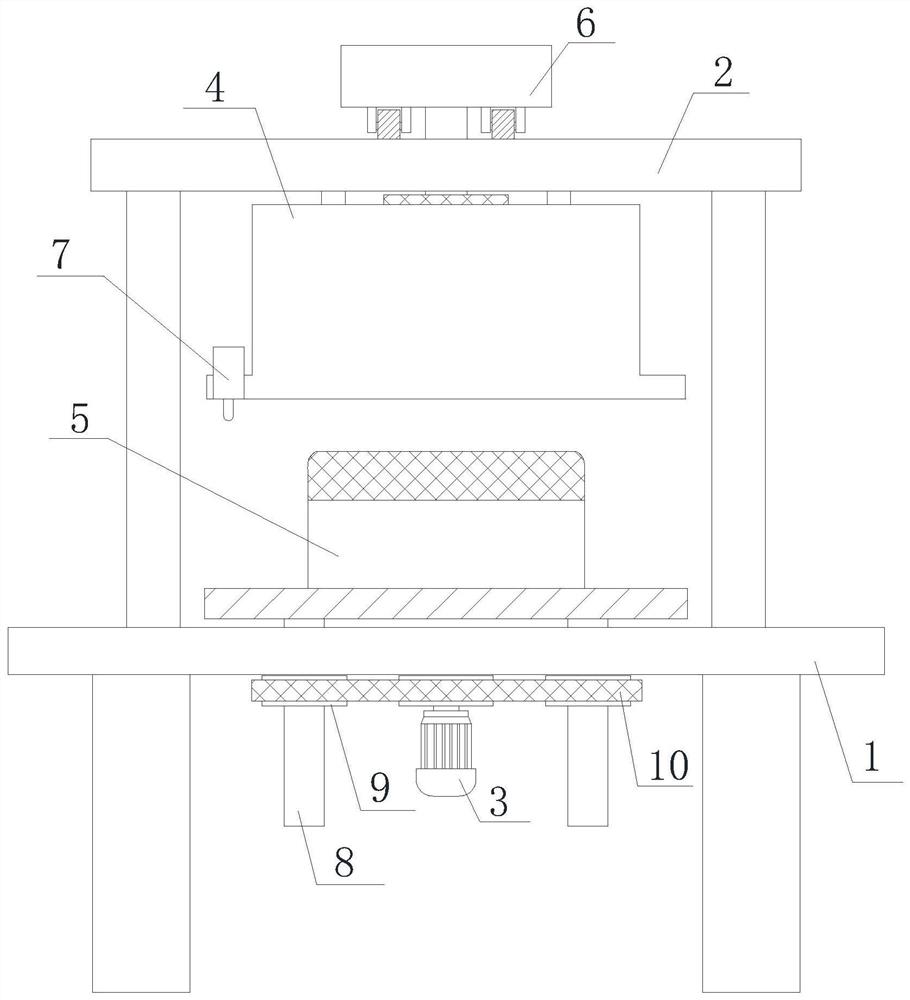
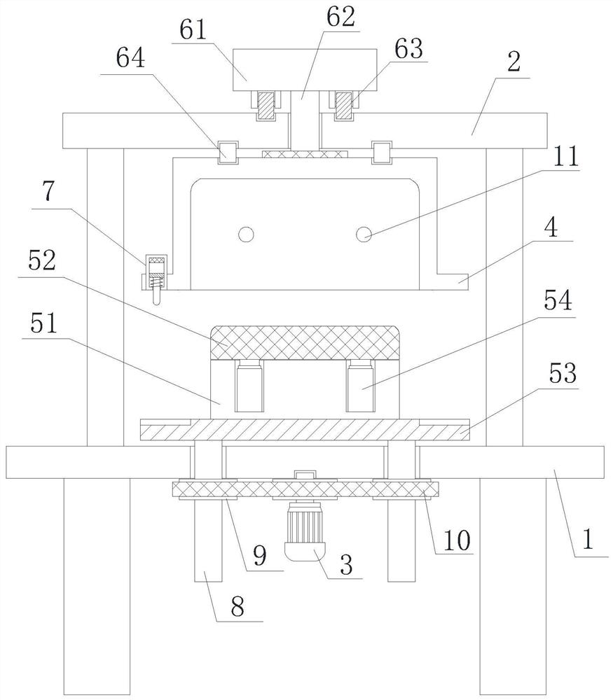
[0028] Refer to attached Figure 1-2 , a kind of quick release device for household appliance plastic parts mold provided by an embodiment of the present invention, comprises processing platform 1, a plurality of supporting feet installed on the lower end of processing platform 1 and the frame 2 installed on the upper end of processing platform 1,...


PUM


Abstract

The invention relates to the technical field of plastic mold equipment, in particular to a rapid ejection device for plastic parts molds of household appliances, comprising a processing platform, a plurality of supporting feet installed at the lower end of the processing platform, and a frame installed at the upper end of the processing platform. An upper concave die is arranged on the inner top wall, a shrinking device is installed on the upper part of the upper concave die, a lower punch component is arranged below the upper die, and the lower end of the lower punch component is symmetrically installed with two A ball screw, the lower end of the ball screw penetrates the side wall of the processing platform and is threadedly sleeved with a first sprocket. The invention overcomes the deficiencies of the prior art, has a reasonable design and a compact structure, and effectively solves the problem that after the plastic parts are formed, the processing personnel need to manually remove the plastic parts. It is not only easy to damage the plastic parts during operation, but also reduces the problem of processing efficiency.

Description

technical field [0001] The invention relates to the technical field of plastic mold equipment, in particular to a quick ejection device for a plastic part mold of a household appliance. Background technique [0002] Home appliance is the abbreviation of household appliances. With the continuous development of my country's economy and the continuous improvement of people's living standards, household appliances are becoming more and more complete. The demand for home appliances continues to rise. With the increase in the production of home appliances, the demand for There are more and more plastic parts, and the quality requirements are getting higher and higher. [0003] Plastic molds are tools that are matched with plastic molding machines in the plastic processing industry to give plastic products a complete configuration and precise dimensions. Due to the variety of plastics and processing methods, and the structures of plastic molding machines and plastic products, the t...

Claims


Application Information

Patent Timeline
Patent Type & Authority Patents(China)
IPC IPC(8): B29C45/26B29C45/40B29C45/64B29L31/34
Inventor 钱国宏李保朝
Owner 安徽皖精模具科技有限公司
Why Eureka
Try Eureka