Automatic unwinding and winding device and automatic unwinding and winding method

An automatic unloading and film roll technology, which is applied in the direction of winding strips, transportation and packaging, thin material processing, etc., can solve the problems of heavy load, low degree of automation, and high labor intensity of workers, so as to simplify the structure and reduce equipment required effect

Active Publication Date: 2019-05-07
GUANGDONG JINMING MACHINERY
View PDF6 Cites 14 Cited by
  • Summary
  • Abstract
  • Description
  • Claims
  • Application Information

AI Technical Summary

Problems solved by technology

[0004] The traditional coil unloading and core loading processes are mainly carried out manually, with a low degree of automation and high labor intensity
In order to improve the automation of the coil unloading and core loading process, the applicant continued to explore and applied for the CN201611060866.7 invention patent, but there are still many things to be improved in the above patent: 1. Failed to realize automatic deflation, let alone For automatic inflation, it can only be inflated and deflated by workers; 2. The top panel of the carrying trolley carrying the film roll must be able to lift accurately so that the winding shaft can be accurately inserted into the paper core tube when the core is loaded. The panel has a large area and must be driven by four vertical motion mechanisms arranged under the corners of the top panel, and the four vertical motion mechanisms must be synchronized to realize the synchronous rise or fall of the top panel as a whole. Therefore, it is required The vertical movement mechanism is relatively precise, but on the other hand, when the carrying trolley carries the film roll, its load capacity is large, so the vertical movement mechanism is required to be relatively heavy and strong. The production cost of the vertical movement mechanism of the top panel is often high; 3. Not only the carrying trolley is required, but also the core pulling trolley is required, that is, two trolleys are required, and each trolley needs to be equipped with a corresponding track; 4. The degree of automation is still to be determined improve

Method used


Image

  • Automatic unwinding and winding device and automatic unwinding and winding method
  • Automatic unwinding and winding device and automatic unwinding and winding method
  • Automatic unwinding and winding device and automatic unwinding and winding method

Examples


Embodiment 1

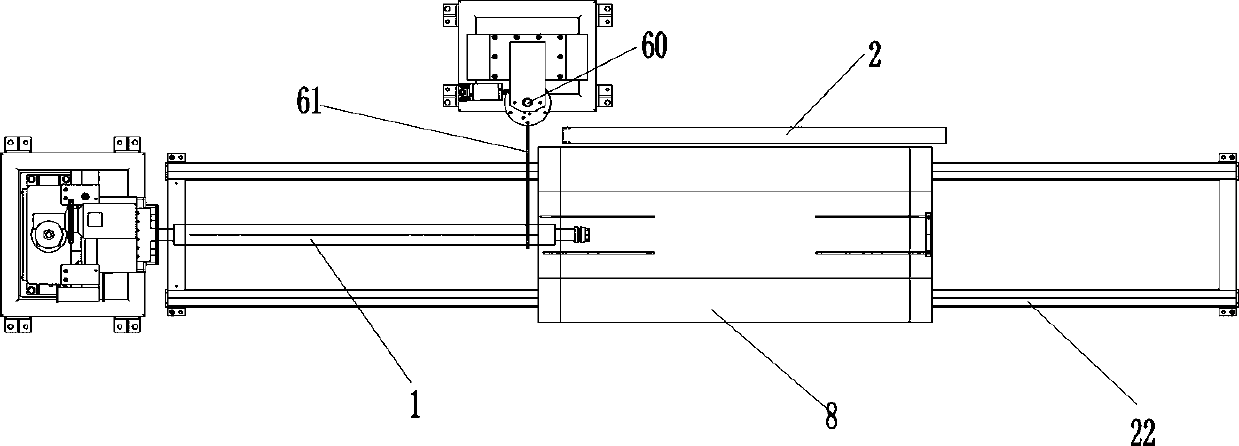
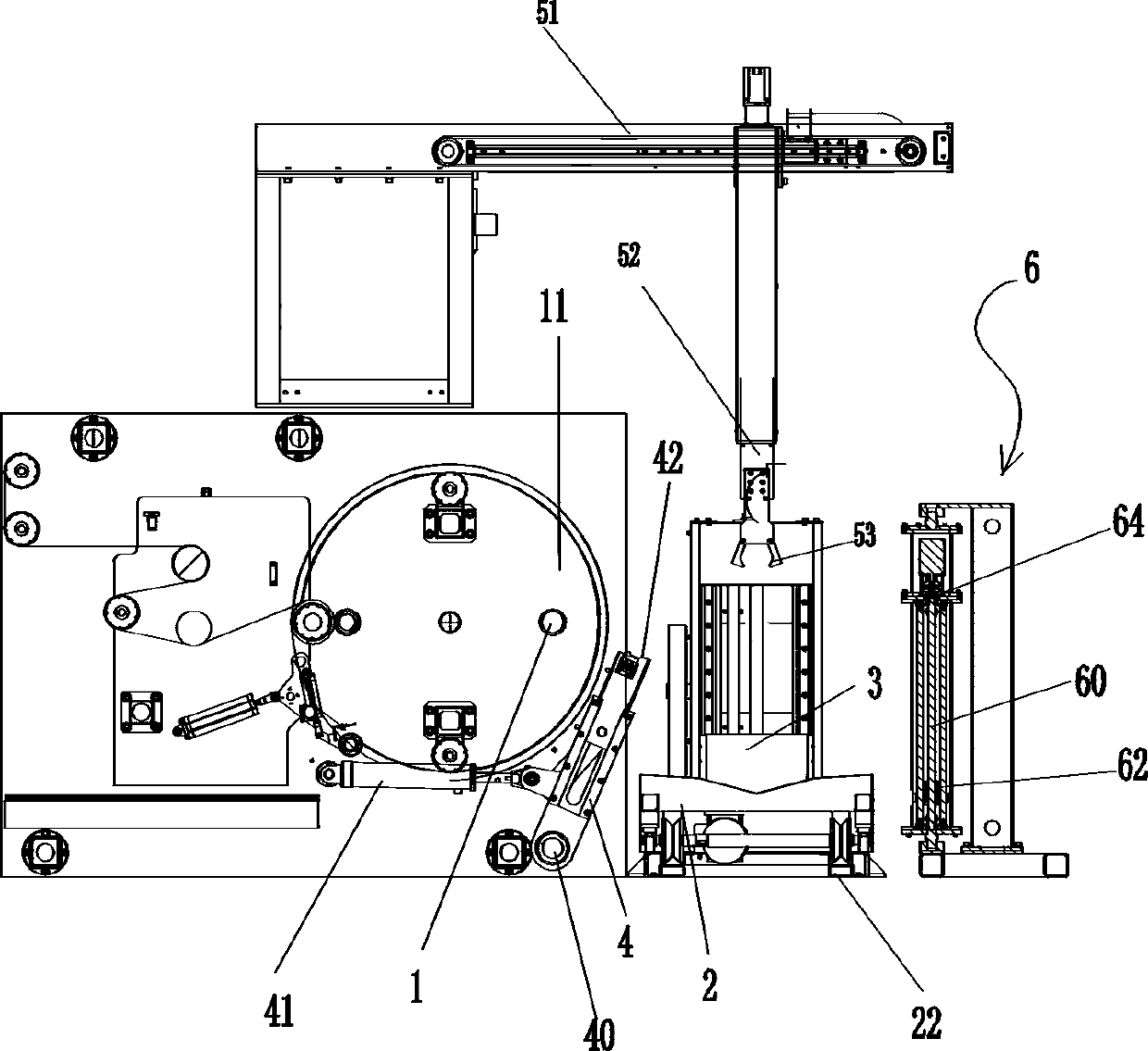
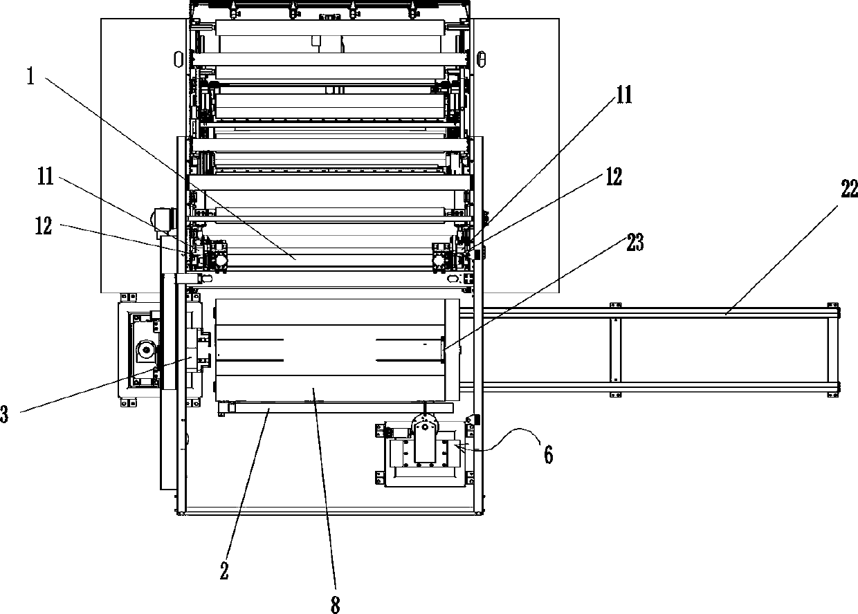
[0077] An automatic unwinding core device, comprising two left and right winding shaft supports 11, an inflatable winding shaft 1 is arranged between the left and right two winding shaft supports 11, and the left and right ends of the winding shaft 1 are installed on the left and right sides respectively. On the first rewinding shaft support 11, the central axis of the rewinding shaft 1 extends laterally. Overlapping with the central axis of the winding shaft 1, the inner cavity 120 of the shaft sleeve has a taper corresponding to the end of the winding shaft; the shaft sleeve 12 is axially movably installed on the corresponding side of the winding shaft support 11, and each winding shaft The support 11 is also provided with a first cylinder that drives the shaft sleeve 12 on the corresponding side to move laterally, and each shaft sleeve 12 forms a movable plug-in relationship with the end of the winding shaft on the corresponding side, as figure 1 , figure 2 , image 3 , ...

Embodiment 2

[0086] A method for automatically unloading cores, which is characterized in that the automatic unloading cores device of Embodiment 1 is adopted, and includes the following steps in sequence:

[0087] (1) When the film roll 8 reaches the set length and is ready to be unloaded, the film roll 8 is wound outside the paper core tube, and the paper core tube is set outside the inflatable reel shaft 1, and the reel shaft 1 is in the expansion state. Tight state and closely combined with the paper core tube, the left and right ends of the winding shaft 1 are respectively inserted in the bushings 12 on the corresponding sides, as Figure 4 Shown; Carrying trolley 2 is positioned at the rear bottom of take-up shaft 1, as figure 1 , figure 2 , image 3 As shown, the two unloading swing arms 4 are in a backward tilting state, as Figure 7 As shown, the support arm support 62 is at the lower end of its vertical movement track, and the length of the horizontal support arm 61 is in a h...


PUM


Abstract

The invention provides an automatic unwinding and winding device. The automatic unwinding and winding device comprises a left winding shaft support and a right winding shaft support, wherein a clamping assembly is further arranged behind the left winding shaft support, a clamping plate support is further provided with an air nozzle connector and a proximity switch used for sensing the position ofthe winding shaft, the left end of a gas nozzle joint is connected with a two-way electromagnetic valve, a transverse guide rail which transversely extends is arranged on the right side of the clamping assembly, a carrying trolley is installed on the transverse guide rail, the carrying trolley is further provided with a left unwinding swing arm, a right unwinding swing arm, a left longitudinal lifting rail and the right longitudinal lifting rail, a vertical lifting arm can be installed on each longitudinal lifting rail in a sliding mode, and a mechanical clamping hand is installed at the lowerend of each vertical lifting arm; and a supporting arm assembly is further arranged beside the transverse guide rail. The invention further provides an automatic unwinding and winding method. The device has the advantages that the automation degree is high, a vehicle roof panel does not need to be lifted, and the structure is compact.

Description

technical field [0001] The invention belongs to the technical field of film winding, and in particular relates to an automatic unwinding core device and an automatic unwinding core method. Background technique [0002] After the film is produced, it is usually wound up into a coil using a winding device. During the winding process, the position of the winding shaft is called the winding position, and the paper core tube sleeved on its outer periphery is driven by the winding shaft to rotate continuously, so that the film material is continuously rolled onto the paper core tube to form a film roll. The specifications of the paper core tube are standard specifications. When the film roll reaches the set length and the film roll reaches the set diameter, it is necessary to remove the film roll from the winding position and extract the film roll (together with the paper core) from the winding shaft. This process is called " unload". After the unloading is completed, it is nec...

Claims


Application Information

Patent Timeline
Patent Type & Authority Applications(China)
IPC IPC(8): B65H19/30B65H75/24B65H18/08
CPCB65H75/24B65H18/08B65H19/30
Inventor 陈俊鸿杨煜新林旭
Owner GUANGDONG JINMING MACHINERY
Why Eureka
Try Eureka