Ultra-high pressure unloading valve

An unloading valve, ultra-high pressure technology, applied in the direction of fluid pressure actuation device, fluid pressure actuation system components, servo motor components, etc., can solve problems such as vaporization and erosion, and achieve the effect of solving erosion and vaporization problems.

Pending Publication Date: 2019-05-07
GUANGDONG NACRE HYDRAULIC CO LTD
View PDF8 Cites 2 Cited by
  • Summary
  • Abstract
  • Description
  • Claims
  • Application Information

AI Technical Summary

Problems solved by technology

[0004] In order to solve the problems of erosion and vaporization during direct unloading in the existing ultra-high pressure hydraulic system, the present invention provides an ultra-high pressure unloading valve

Method used


Image

  • Ultra-high pressure unloading valve
  • Ultra-high pressure unloading valve
  • Ultra-high pressure unloading valve

Examples


Embodiment Construction

[0018] The present invention will be further described below in conjunction with the accompanying drawings.

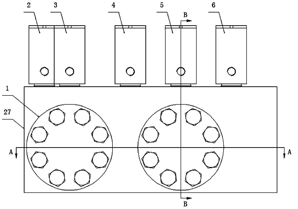
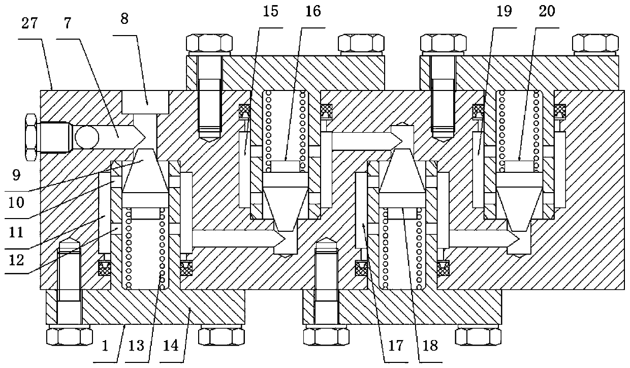
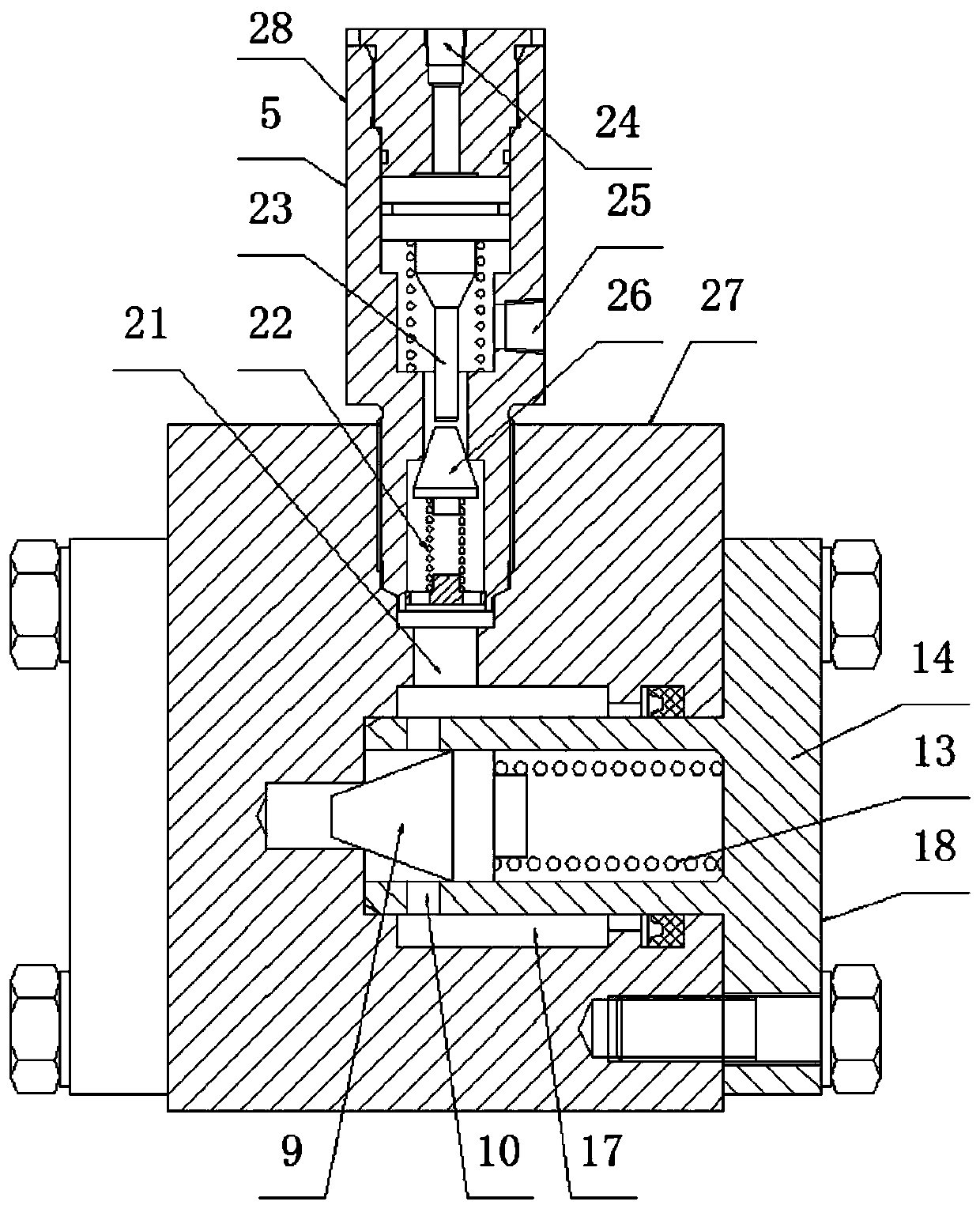
[0019] Preferably, an ultra-high pressure unloading valve includes a main valve body 27, and the main valve body 27 is provided with a plurality of sequentially connected pressure reducing valves that can be decompressed step by step, as described in this preferred embodiment The pressure reducing valve is provided with 4, and described pressure reducing valve comprises P1 cavity pressure reducing valve 1, P2 cavity pressure reducing valve 16, P3 cavity pressure reducing valve 18 and P4 cavity pressure reducing valve 20, described pressure reducing valve Corresponding chambers are provided on the outside, and the chambers include P1 chamber 11, P2 chamber 15, P3 chamber 17 and P4 chamber 19, and the decompression valves are connected in series through decompressible chambers and pipelines. Together, the P1 cavity pressure reducing valve 1 communicates with the pressure...


PUM


Abstract

The invention discloses an ultra-high pressure unloading valve, and relates to a valve unloading device. The ultra-high pressure unloading valve comprises a main valve body, wherein a plurality of pressure reducing valves which sequentially communicate with one another and can reduce pressure step by step are arranged in the main valve body; the pressure reducing valves communicate with one another through a pressure reducing chamber and pipelines; the main valve body is provided with a plurality of one-way valves for balancing the pressure of the pipelines in front of the corresponding pressure reducing valve; the one-way valves communicate with the chamber through a connecting channel; and connecting pipelines communicate with a control oil openings in the upper ends of the one-way valves. By connecting the pressure reducing valves in series, the ultra-high pressure liquid in the pressure reducing valves can be subjected to pressure reducing in stages so as to reduce the flow rate ofliquid at a nozzle of the unloading valve, the pressure difference at the two ends of an unloading opening of the unloading valve is reduced, the pressure of the ultra-high pressure liquid is reducedto a certain range after penetrating through the unloading valve, and the erosion and vaporization problems generated during direct unloading in the prior art is solved; and in addition, the pressuredifference of the liquid in front of the pressure reducing valves is maintained as much as possible through the one-way valves, so that the pressure reducing valves normally work.

Description

technical field [0001] The invention belongs to a valve unloading device, in particular to an ultra-high pressure unloading valve. Background technique [0002] At present, in the hydraulic system with large flow and working pressure between 150MPa and 400MPa, the existing unloading scheme is usually direct unloading, that is, the ultra-high pressure liquid medium is directly discharged through the hydraulic control check valve. The pressure of the ultra-high pressure liquid medium suddenly drops to 0MPa, so when the liquid medium passes through the valve hole, due to the large pressure drop, the flow velocity suddenly increases, and the force of the liquid medium on the unloading hole is very large, far exceeding the bearing limit of existing materials. Then unloading in this way has the problem that the unloading hole is easily damaged by erosion, which shortens the service life; at the same time, the pressure drop is too large, because the energy release is very large, an...

Claims


Application Information

Patent Timeline
Patent Type & Authority Applications(China)
IPC IPC(8): F15B13/02F15B21/047
Inventor 付巍黄凯
Owner GUANGDONG NACRE HYDRAULIC CO LTD
Why Eureka
Try Eureka