Recyclable rocket landing working condition simulation equipment based on rope drive parallel robot

A technology of working condition simulation and robotics, which is applied in the aerospace field, can solve the problems that the rocket process cannot be simulated and verified, and the landing conditions of the recoverable rocket cannot be simulated.

Active Publication Date: 2019-05-07
HARBIN INST OF TECH
View PDF6 Cites 10 Cited by
  • Summary
  • Abstract
  • Description
  • Claims
  • Application Information

AI Technical Summary

Problems solved by technology

[0003] The purpose of the present invention is to solve the problem that the existing prototype of the landing support mechanism cannot simulate the landing process of the recoverable rocket due

Method used


Image

  • Recyclable rocket landing working condition simulation equipment based on rope drive parallel robot
  • Recyclable rocket landing working condition simulation equipment based on rope drive parallel robot
  • Recyclable rocket landing working condition simulation equipment based on rope drive parallel robot

Examples


specific Embodiment approach 1

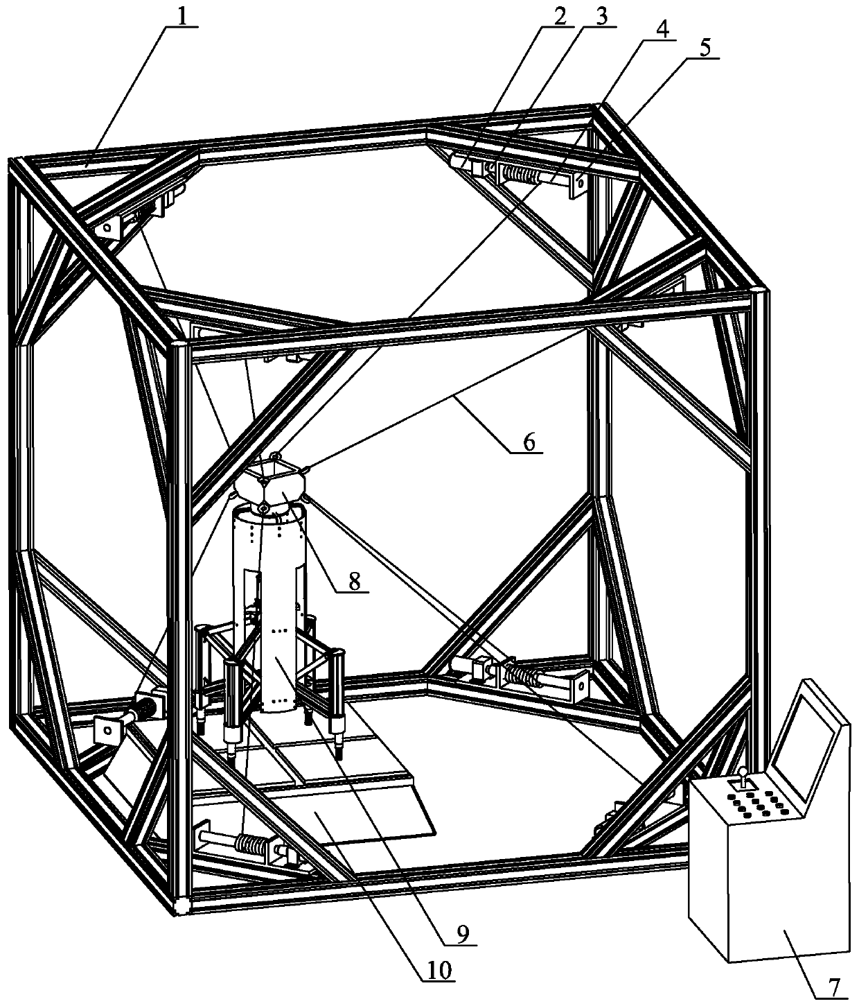
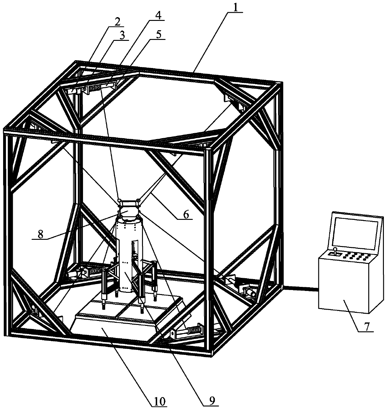
[0014] Specific implementation mode one: combine Figure 1 to Figure 6 Describe this embodiment, a kind of retrievable rocket landing condition simulation equipment based on a rope-driven parallel robot in this embodiment, it includes an attitude control device, a suspension unlocking mechanism and a measuring device, and the attitude control device includes a support frame 1 and a plurality of Drive unit, a plurality of drive units are installed on the eight corners of the support frame 1; the measuring device includes an operation control machine 7 and an impact acceleration test platform 10, the impact acceleration test platform 10 is installed in the support frame 1, and the operation control machine 7 is respectively Control the action of the drive unit and the suspension unlocking mechanism, the suspension unlocking mechanism is installed on the impact acceleration test platform 10; the suspension unlocking mechanism includes a suspension release mechanism 8 and a landing...

specific Embodiment approach 2

[0020] Specific implementation mode two: combination Figure 1 to Figure 2 Describe this embodiment, the driving unit of this embodiment includes a drive motor 2 and a rope winding mechanism, the rope winding mechanism includes a coupling 3, a rope winding rod 4, a bearing seat 5 and a steel wire rope 6, and the bearing seat 5 is installed on the support frame 1 Above, the rope-winding rod 4 is installed on the bearing housing 5, the drive motor 2 is installed on the support frame 1, the drive motor 2 and the rope-winding rod 4 are connected by a coupling 3, and one end of the wire rope 6 is connected to the rope One end of the rotating rod 4 is connected, and the other end of the wire rope 6 is connected with the suspension release mechanism 8 . With such arrangement, the retraction and release of the rope can be precisely controlled, and the movement of the predetermined trajectory of the rocket body can be completed through the coupling action of multiple groups of rope-rai...

specific Embodiment approach 3

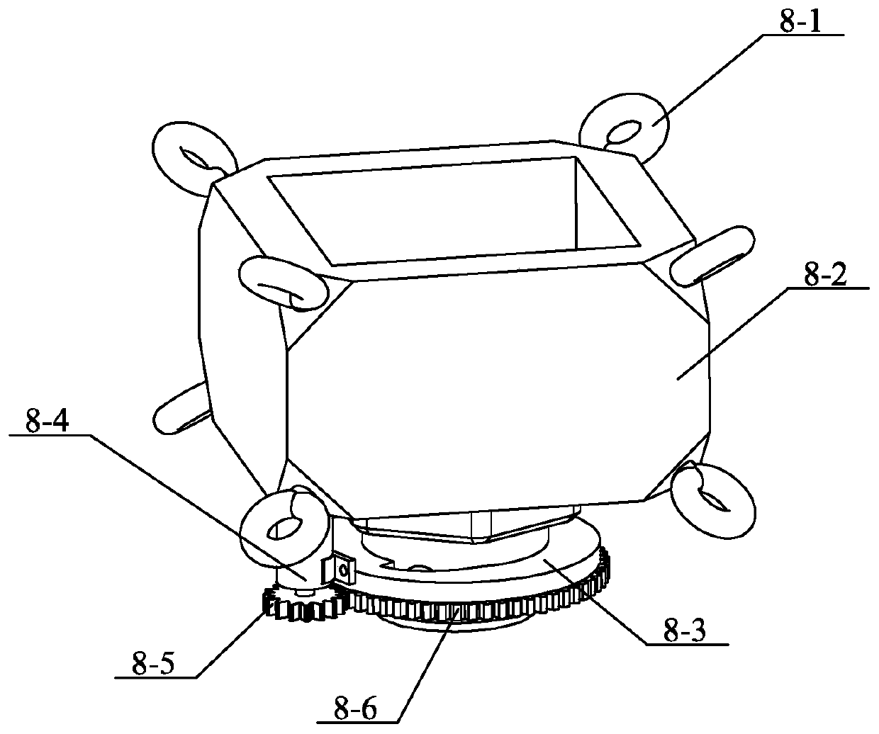
[0021] Specific implementation mode three: combination image 3 and Figure 4 Describe this embodiment, the suspension release mechanism 8 of this embodiment includes a control box 8-2, an unlocking flange 8-3, an unlocking assembly and a plurality of lifting lugs 8-1, and a plurality of lifting lugs 8-1 are installed on the control box On the outer wall of 8-2, the unlocking flange 8-3 is installed on the lower end surface of the control box 8-2, and the unlocking assembly is installed on the lower end of the unlocking flange 8-3. With this setting, the release of the rocket landing support mechanism is realized, and the simulation of different working conditions is completed. Other compositions and connections are the same as those in Embodiment 1 or 2.


PUM


Abstract

The invention discloses recyclable rocket landing working condition simulation equipment based on a rope drive parallel robot, and relates to a recyclable rocket landing working condition simulation device. The invention aims to solve the problem that an existing landing support mechanism prototype cannot simulate recoverable rocket landing working condition, so that the process of actual return of the rocket can not be simulated and verified. A posture control device comprises a supporting frame and a plurality of driving units, the plurality of driving units are arranged on the eight vertexangles of the supporting frame; a measuring device comprises an operation control machine and an impact acceleration test platform, the impact acceleration test platform is installed in the support frame, a suspension unlocking mechanism is installed on the impact acceleration test platform, the suspension unlocking mechanism comprises a suspension release mechanism and a landing support mechanism, the landing support mechanism is installed on the impact acceleration test platform, the suspension release mechanism is installed on the landing support mechanism, and the suspension releasing mechanism is connected with the driving units through a steel wire rope. The equipment is applied to the field of aerospace.

Description

technical field [0001] The invention relates to a retrievable rocket landing condition simulating device, in particular to a retrievable rocket landing condition simulating device based on a rope-driven parallel robot, belonging to the technical field of aerospace. Background technique [0002] At present, most rockets are launched for one-time use. With the rapid development of recyclable rockets, the prospect of recyclable work in the future is good. The premise of a stable landing of a recyclable rocket is to have a highly reliable landing support mechanism for support. A highly reliable landing support mechanism is of great significance, and the development of the landing support mechanism prototype requires experimental verification under different working conditions to meet the technical needs of the rocket in the actual return process, and the rocket prototype needs to be simulated under different working conditions on the ground Design a control platform with six deg...

Claims


Application Information

Patent Timeline
IPC IPC(8): F42B35/00B25J9/10B25J9/00
Inventor 于海涛高海波田保林刘振李楠邓宗全
Owner HARBIN INST OF TECH
Why Eureka
Try Eureka