BUC connection structure and moving medium satellite system

A connection structure and satellite antenna technology, which is applied in the direction of antenna grounding switch structure connection, radiation unit cover, electrical components, etc., can solve the problem of improving the energy consumption of the satellite system in motion

Active Publication Date: 2019-05-07
睿高(广州)通信技术有限公司
7 Cites 0 Cited by

AI-Extracted Technical Summary

Problems solved by technology

[0004] In the use of the satellite system in motion, the power of the BUC (up conversion power amplifier) ​​is generally increased to in...

Method used

Above-mentioned BUC connection structure, flat panel satellite antenna 100 and BUC200 are directly connected with feed source input end by transmitting waveguide end 211 to realize signal transmission. The general flat satellite antenna 100 and the BUC 200 are connected through a waveguide with joints at both ends to realize signal transmission. Compared with the general connection structure between the flat satellite antenna 100 and the BUC, this application omits the waveguide and the joints arranged at both ends of the waveguide, shortens the signal transmission path between the flat satellite antenna 100 and the BUC200, and shortens the The signal transmission path between the two reduces the standing wave ratio of the transmitted signal, thereby reducing the energy consumption demand of the BUC200. At the same time, the direct connection structure between the flat satellite antenna 100 and the BUC200 and the feed input end through the transmitting waveguide end 211 simplifies the connection structur...

Abstract

The invention relates to a BUC connection structure and a moving medium satellite system. The BUC connection structure comprises a flat satellite antenna and a BUC, the flat satellite antenna is provided with a feed source input end; the BUC is provided with a transmitting waveguide end which is directly connected with the feed source input end; the flat satellite antenna and the BUC are directlyconnected with the feed source input end through the transmitting waveguide end to achieve signal transmission. A general flat satellite antenna and the BUC are connected through a waveguide tube having two ends with joints to achieve signal transmission. Compared to a connection structure of a general flat satellite antenna and the BUC, the BUC connection structure omits the joints arranged at two ends of the waveguide tube to shorten the path of the signal transmission between the flat satellite antenna and the BUC and reduce the standing-wave ratio of the transmission signals through shortening the path of the transmission signals therebetween so as to reduce the energy consumption demand of the BUC.

Application Domain

Radiating element housingsAntennas earthing switches association

Technology Topic

PhysicsSatellite +3

Image

  • BUC connection structure and moving medium satellite system
  • BUC connection structure and moving medium satellite system
  • BUC connection structure and moving medium satellite system

Examples

  • Experimental program(1)

Example Embodiment

[0023] In order to facilitate the understanding of the present invention, the present invention will be described more fully below with reference to the relevant drawings. The preferred embodiments of the present invention are shown in the drawings. However, the present invention can be implemented in many different forms and is not limited to the embodiments described herein. On the contrary, the purpose of providing these embodiments is to make the disclosure of the present invention more thorough and comprehensive.
[0024] It should be noted that when an element is referred to as being "fixed to" another element, it can be directly on the other element or a central element may also exist. When an element is considered to be "connected" to another element, it can be directly connected to the other element or an intermediate element may be present at the same time. In contrast, when an element is referred to as being "directly on" another element, there are no intervening elements. The terms "vertical", "horizontal", "left", "right" and similar expressions used herein are for illustrative purposes only and are not meant to be the only embodiments.
[0025] Unless otherwise defined, all technical and scientific terms used herein have the same meaning as commonly understood by those skilled in the technical field of the present invention. The terms used in the description of the present invention herein are only for the purpose of describing specific embodiments, and are not intended to limit the present invention. The term "and/or" as used herein includes any and all combinations of one or more related listed items.
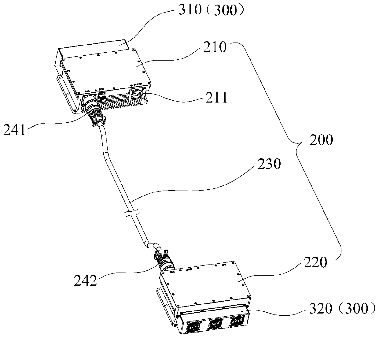
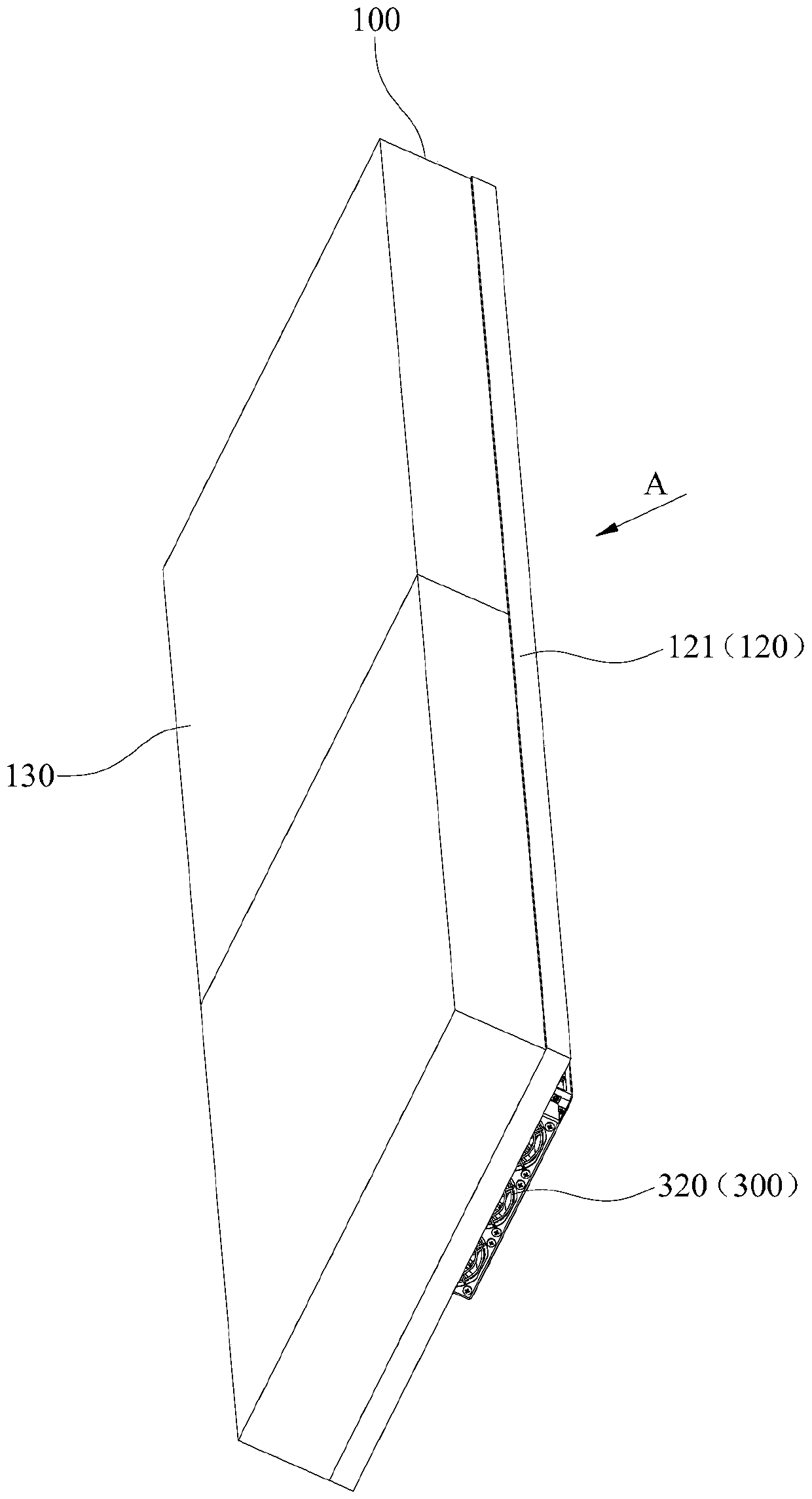
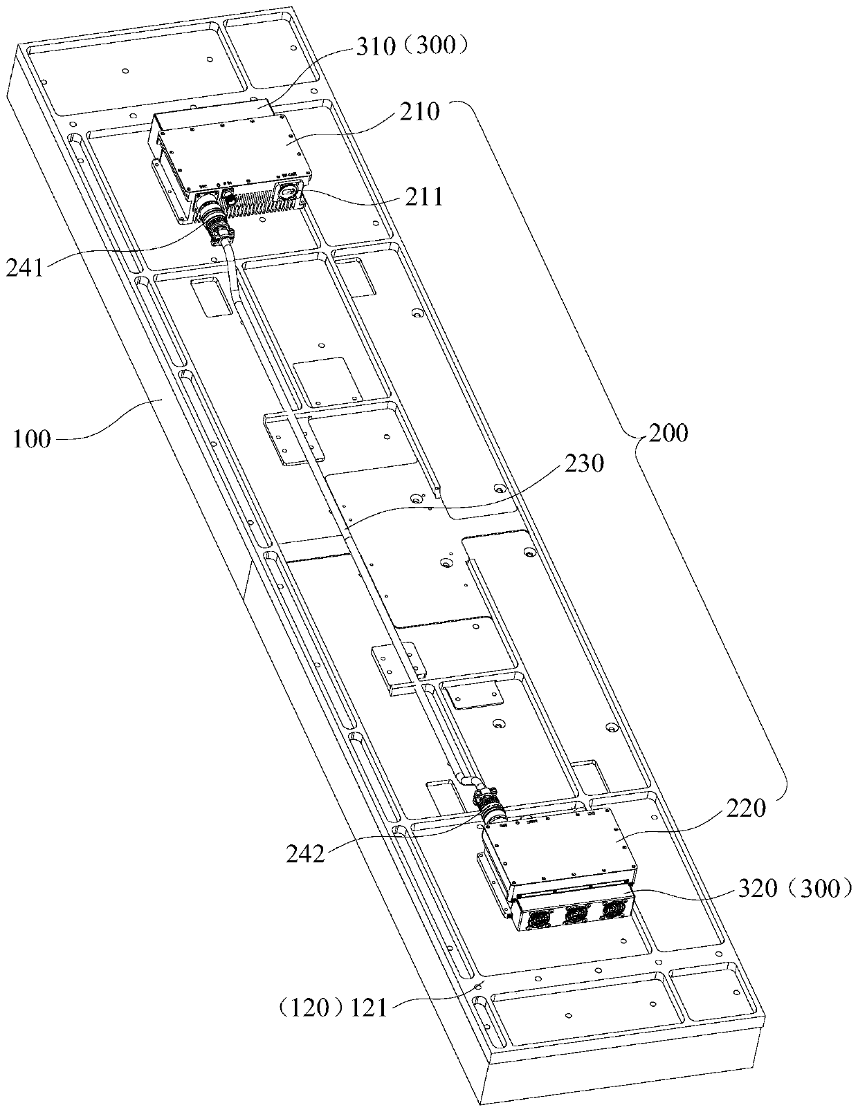
[0026] Combine figure 1 , figure 2 and image 3 As shown, in one embodiment, a BUC connection structure is provided, including a flat-panel satellite antenna 100 and a BUC200. The flat-panel satellite antenna 100 is provided with a feed input terminal (not shown in the figure); the BUC200 is provided with a transmitter The waveguide end 211 is directly connected to the input end of the feed source.
[0027] In the above-mentioned BUC connection structure, the flat satellite antenna 100 and the BUC 200 are directly connected to the feed input terminal through the transmitting waveguide terminal 211 to realize signal transmission. The general flat satellite antenna 100 and the BUC 200 are connected through a waveguide with joints at both ends to realize signal transmission. Compared with the general flat satellite antenna 100 and the BUC connection structure, the waveguide and the joints provided at both ends of the still tube are omitted in this application, and the signal transmission path between the flat satellite antenna 100 and the BUC 200 is shortened. The signal transmission path between the two reduces the standing wave ratio of the transmission signal, thereby reducing the energy consumption requirements of the BUC200. At the same time, the structure in which the flat satellite antenna 100 and the BUC 200 are directly connected to the feed input terminal through the transmitting waveguide end 211 simplifies the connection structure of the BUC 200 and the flat satellite antenna 100 and saves costs.
[0028] In an embodiment, the BUC 200 includes a detachable BUC transmitting module 210 and a BUC functional module 220, the BUC transmitting module 210 and the BUC functional module 220 are signal-connected, and the BUC transmitting module 210 is provided with the transmitting waveguide end 211. When the BUC200 and the flat satellite antenna 100 are installed in the moving satellite system, since the BUC transmitting module 210 and the BUC function module 220 can be separated, the BUC transmitting module 210 and the BUC function module can be combined according to the spatial structure of the moving satellite system 220 is arranged separately, so that the structure of the satellite system in motion can be compact, and the overall structure size of the satellite system in motion can be reduced.
[0029] In an embodiment, the BUC connection structure further includes a signal transmission line 230. The two ends of the signal transmission line 230 are respectively connected to the BUC transmission module 210 and the BUC function module 220 to transmit between the BUC transmission module 210 and the BUC function module 220. signal of. The signal transmission line 230 has a simple structure for transmitting signals between the BUC transmitting module 210 and the BUC function module 220, and the signal transmission is stable and reliable.
[0030] In an embodiment, both ends of the signal transmission line 230 are respectively provided with a first plug connector 241 and a second plug connector 242. The first plug connector 241 is mated with the BUC transmitting module 210, and the second plug connector 242 is mated with the BUC function module 220. During installation, the first plug connector 241 and the second plug connector 242 are used to plug and connect the BUC transmitter module 210, the BUC function module 220, and the signal transmission line 230. The installation operation is simple.
[0031] In one embodiment, the signal transmission line 230 is a shielded cable, and the first plug connector 241 and the second plug connector 242 are both shielded connectors. When the signal transmission line 230 is a shielded cable, and the first plug connector 241 and the second plug connector 242 are both shielded connectors, both the shielded cable and the shielded connector can reduce the interference of signal transmission to the flat satellite antenna 100, thereby ensuring The flat satellite antenna 100 can work normally and stably.
[0032] In one embodiment, the flat satellite antenna 100 is provided with a mounting plate 120, and the BUC 200 is set on the mounting plate 120 and can move with the flat satellite antenna 100. The BUC200 is arranged on the mounting board 120, so that the BUC200 can move with the flat satellite antenna 100, which avoids the problem of loose connection between the BUC200 and the flat satellite antenna 100 due to relative movement, and thereby connects the transmitting waveguide end 211 to the feed input end Stable and reliable.
[0033] In an embodiment, the mounting plate 120 is a metal mounting plate 121, and the BUC 200 and the metal mounting plate 121 can be thermally conductively fitted. When the mounting board 120 is a metal mounting board 121, the metal mounting board 121 can increase the heat dissipation area, thereby reducing the operating temperature of the BUC200.
[0034] Specifically, in this embodiment, the mounting board 120 is located on the back of the flat satellite antenna 100. It should be explained that the flat satellite antenna 100 is provided with a transmitting surface 130 for transmitting and receiving signals, and the back refers to the side of the flat satellite antenna 100 facing away from the transmitting surface 130. This can prevent the BUC200 from affecting the signal transmission of the flat satellite antenna 100. In addition, in other embodiments, the aforementioned mounting plate 120 may also be located at other parts of the flat satellite antenna 100. For example, the mounting plate 120 is located between the back of the flat satellite antenna 100 and the transmitting surface 130.
[0035] In addition, it should be noted that the aforementioned mounting plate 120 may be a part of the flat-panel satellite antenna 100. Of course, the aforementioned mounting plate 120 may also be a plate or a plate frame mounted on the flat-panel satellite antenna 100.
[0036] In an embodiment, the BUC connection structure further includes a heat exchange fan 300, and the heat exchange fan 300 is arranged corresponding to the BUC 200 to accelerate the heat dissipation of the BUC 200. In use, the heat exchange fan 300 can accelerate the gas flow rate in the environment where the BUC200 is located, thereby reducing the temperature of the environment where the BUC200 is located.
[0037] Further, in an embodiment, the heat exchange fan 300 includes a first heat exchange fan 310 corresponding to the BUC emission module 210 and a second heat exchange fan 320 corresponding to the BUC function module 220.
[0038] Specifically, the first heat exchange fan 310 and the second heat exchange fan 320 are both arranged on the mounting plate 120.
[0039] Combine Figure 4 As shown, in another embodiment, a satellite system in motion is provided, including a base 410 and the BUC connection structure described in any of the foregoing embodiments, and the BUC connection structure is rotatably disposed on the base 410. When the BUC connection structure is used in the mobile satellite system, the base 410 can carry and install the BUC connection structure; at the same time, by rotating the BUC connection structure, the alignment angle between the flat satellite antenna 100 and the satellite can be changed to achieve the tracking of the flat satellite antenna 100 The purpose of the satellite.
[0040] It should be noted that a rotating bracket 420 is provided between the base 410 and the BUC connecting structure, and the rotating bracket 420 can drive the BUC connecting structure to rotate so that the flat satellite antenna 100 can track the satellite. The rotating bracket 420 is generally a two-axis rotating bracket, and the two-axis rotating bracket can move the BUC connection structure in an arc-shaped surface.
[0041] Specifically, the two-axis rotating bracket can learn from the structure of the universal joint. Of course, in order to facilitate the adjustment of the position of the BUC connection structure, the two-axis rotating bracket is equipped with two motors, through which the two-axis rotating bracket can be controlled to rotate in two directions.
[0042] Specifically, in an embodiment, the rotating bracket 420 is connected to the mounting plate 120 to drive the flat satellite antenna 101. The BUC transmitting module 210 and the BUC function module 220 are spaced apart so that the mounting plate 120 reserves a space for connecting with the rotating bracket 420; at the same time, this method can also use the BUC transmitting module 210 and the BUC function module 220 to balance the force of the rotating bracket 420.
[0043] In one embodiment, the mobile satellite system further includes a radome 430 covering the BUC connection structure, and the radome 430 is connected to the base 410. The radome 430 can effectively protect the BUC connection structure and reduce the influence of the external environment on the BUC connection structure, thereby ensuring the normal operation of the BUC connection structure.
[0044] The technical features of the above-mentioned embodiments can be combined arbitrarily. In order to make the description concise, all possible combinations of the various technical features in the above-mentioned embodiments are not described. However, as long as there is no contradiction in the combination of these technical features, All should be considered as the scope of this specification.
[0045] The above-mentioned embodiments only express several embodiments of the present invention, and their descriptions are more specific and detailed, but they should not be interpreted as limiting the scope of the invention patent. It should be pointed out that for those of ordinary skill in the art, without departing from the concept of the present invention, several modifications and improvements can be made, and these all fall within the protection scope of the present invention. Therefore, the protection scope of the patent of the present invention should be subject to the appended claims.

PUM

no PUM

Description & Claims & Application Information

We can also present the details of the Description, Claims and Application information to help users get a comprehensive understanding of the technical details of the patent, such as background art, summary of invention, brief description of drawings, description of embodiments, and other original content. On the other hand, users can also determine the specific scope of protection of the technology through the list of claims; as well as understand the changes in the life cycle of the technology with the presentation of the patent timeline. Login to view more.
Why Eureka
Try Eureka