Pole-attached coil of DC motor and its winding method

A DC motor and motor winding technology, which is applied in the manufacture of motor generators, electromechanical devices, electrical components, etc., can solve the problems of easy damage to the insulation of inter-turn intersections, short circuits between turns, and low winding density of turns, so as to facilitate wiring and The effect of installation operation, improving power density, and increasing the number of winding turns

Active Publication Date: 2019-06-25
NEW UNITED RAIL TRANSIT TECH
View PDF6 Cites 0 Cited by
  • Summary
  • Abstract
  • Description
  • Claims
  • Application Information

AI Technical Summary

Problems solved by technology

The existing technical solutions have the following problems: first, the lead-out wires at the head and end of the coil are led out from the inner layer and the outer layer of the coil respectively, and the lead-wire ends are super high along the radial direction of the iron core, and the protruding lead-out wires are easy to rub against the rotor or rub against the yoke Partial interference; Second, the coil is wound on a straight line for direct transition transfer. Due to the presence of hypotenuses in the straight line of the coil, the winding density of the turns is low, which cannot meet the requirements for the number of turns in the limited space of the motor; third, the coil is wound directly and transitions , due to the tension force during winding, the insulation at the intersection between turns is easily damaged, resulting in a short circuit between turns
[0005] Publication No. CN1518191A discloses a concentrated winding stator coil group patent for a rotating electrical machine. Each coil involved in the patent is composed of a multilayer coil including one or more pairs of layered coils; the layered coils include a first layered coil and a Second layer coil; winding the coil wire such that the last turn of the first layer coil is continuous with the first turn of the second layer coil and positioning the ends of the coil wire on and above the bottom of each tooth , so that the two ends serve as the winding start and winding end of each coil, and the transition between turns and layers is transferred at the end of the coil. The coil in this patent has the problem of narrow application range, for example, it is not suitable for The problem of the pole core of the flat structure, because for the pole core of the flat structure, the width of the core is small, and the inter-turn and inter-layer cannot be transferred at the end of the coil but can only be transferred on the straight side

Method used


Image

  • Pole-attached coil of DC motor and its winding method
  • Pole-attached coil of DC motor and its winding method
  • Pole-attached coil of DC motor and its winding method

Examples


Embodiment 1

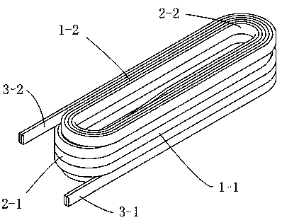
[0058] see Figure 1 to Figure 9 As shown, this embodiment provides a polarized coil of a DC motor, comprising: an elliptical ring body formed by winding one or more parallel motor winding wires; wire 3-1, and the second lead-out wire 3-2 arranged at the end of the motor winding wire. In this embodiment, the structure of two parallel motor winding wires is taken as an example.

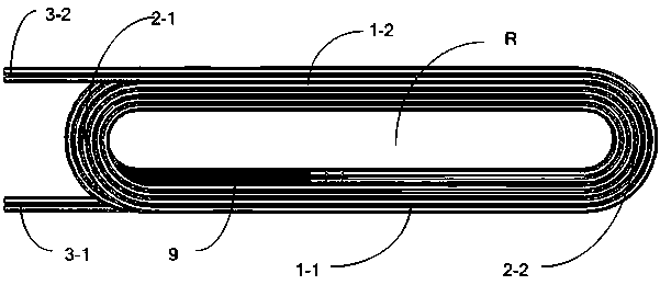
[0059] Specifically, the elliptical ring body includes a forward winding coil group and a reverse winding coil group formed by integral winding; the forward winding coil group and the reverse winding coil group are wound to form a relatively distributed first straight line portion 1- 1 and the second straight part 1-2, and the first arc part 2-1 and the second arc part 2 which are connected to the first straight part 1-1 and the second straight part 1-2 and are relatively distributed -2; the first lead-out line 3-1 is located at the outer end of the elliptical inner hole R of the forward winding coil...

Embodiment approach

[0061] The motor winding wire of this embodiment is preferably a winding wire with its own insulating layer; in an optional embodiment, the winding wire is a double glass fiber-wrapped film-wrapped copper flat wire or a single glass fiber-wrapped film-wrapped copper flat wire. There is no absolute limit to the specific model of the specific double glass fiber wrapped film wrapped copper flat wire or single glass fiber wrapped film wrapped copper flat wire.

[0062] With reference to the drawings of the embodiment, this embodiment takes a pole-attached coil with a three-layer structure as an example, the number of layers of the forward winding coil group is three layers, and the number of layers of the reverse winding coil group is three layers. The first lead-out line 3-1 protrudes from the first straight line 1-1 to the direction in which the first arc-shaped portion 2-1 extends; the second lead-out line 3-2 extends from the second straight line 1-2 to the first arc The direc...

Embodiment 2

[0070] This embodiment provides a method for winding an attached pole coil of a DC motor, which specifically includes:

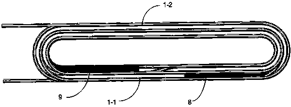
[0071] Step S1: Reserve a section of motor winding wire at one end of one or more parallel motor winding wires to form the reserved motor winding wire 11; the length of the reserved motor winding wire is equal to or greater than that of the reverse winding coil group The sum of the length of the required motor winding wire and the length of the first lead wire 3-1;

[0072] Step S2: Three layers of motor winding wires other than the reserved motor winding wires in the motor winding wires in step S1 are forward wound to form a forward winding coil group; at the end of the motor winding wire of the forward winding coil group, The second lead-out line 3-2;

[0073] Step S3: Reversely wind three layers of the reserved motor winding wire 11 in step S1 to form a reverse winding group; the reverse winding direction of the reverse winding group is the same as that ...


PUM


Abstract

The invention discloses a pole-attached coil of a direct current motor and a winding method thereof, comprising: an elliptical ring body formed by winding one or more parallel motor winding wires; lead-out wire, and a second lead-out wire arranged at the end of the motor winding wire. The elliptical ring body includes a forward winding coil group and a reverse winding coil group formed by integral winding; the forward winding coil group and the reverse winding coil group are wound to form a relatively distributed first straight line part and a second straight line part , and the first arc-shaped portion and the second arc-shaped portion that are connected with the first straight line portion and the second straight line portion and are relatively distributed; At the outer end of the hole, the second lead-out wire is located at the outer end of the elliptical inner hole of the reverse winding coil group away from the elliptical ring body.

Description

technical field [0001] The invention relates to the technical field of motors, in particular to a polarized coil of a DC motor and a winding method thereof. Background technique [0002] As an important part of the DC motor stator, the attached pole coil is mainly used to improve the commutation performance of the motor, also known as the commutation pole coil. [0003] The pole-attached coil of a DC motor is a concentrated winding coil. For a multi-layer multi-turn coil, a formed winding wire with an insulating layer is usually used to wind it on a mold and then put it into the pole core of the motor. The conventional practice is to wind in one direction, and the lead-out wires at the beginning and end are drawn from the inner and outer layers of the coil respectively; the coil winding process is usually a direct transition transfer between turns and layers, and because the width of the DC motor’s attached pole core is small, Turns and layers cannot be transitioned at the ...

Claims


Application Information

Patent Timeline
Patent Type & Authority Patents(China)
IPC IPC(8): H02K3/04H02K15/04
Inventor 曹扬陈锋陈健孙丽娟卢念成吴军徐建洪
Owner NEW UNITED RAIL TRANSIT TECH
Why Eureka
Try Eureka