Winding mold of magnetic pole coil and winding method using the same
A technology for winding molds and magnetic pole coils, which is used in coil manufacturing, motor generators, electrical components, etc., to avoid local convex turns, ensure coil structure, and improve overall compactness.
- Summary
- Abstract
- Description
- Claims
- Application Information
AI Technical Summary
Problems solved by technology
Method used
Image
Examples
Embodiment 1
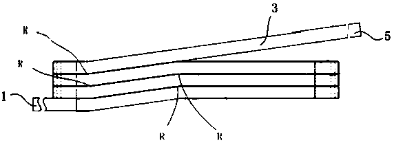
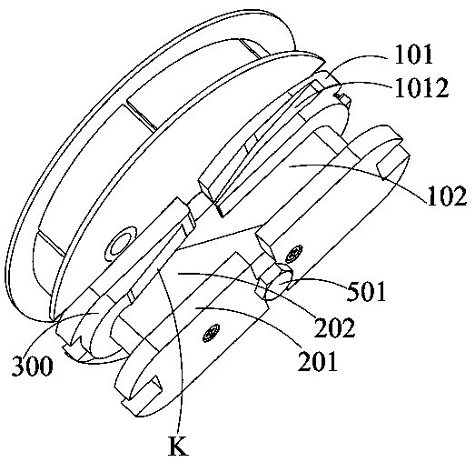
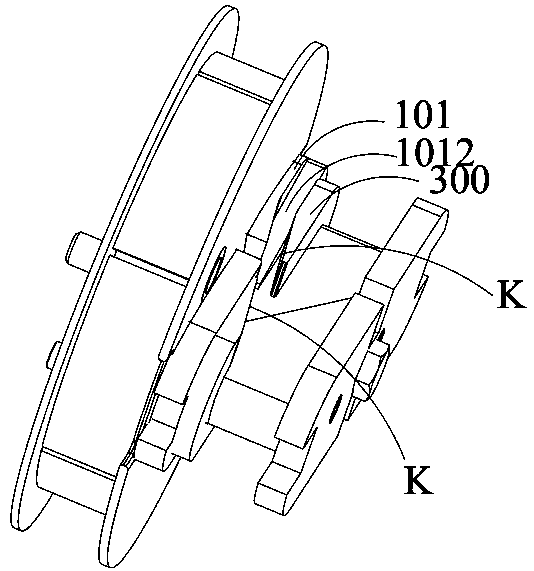
[0052] see Figure 1 to Figure 7 As shown, this embodiment provides a magnetic pole coil winding mold, which is suitable for such as figure 1 As shown in the magnetic pole coil, the magnetic pole coil is formed with a forward winding part and a reverse winding part of the electromagnetic wire during the winding process of the electromagnetic wire, and the lead-out line 1 of the forward winding electromagnetic wire and the reverse winding The lead-out lines 5 of the electromagnetic wires are drawn from the outside of the electromagnetic coil formed by winding (the forward winding and reverse winding here specifically refer to the opposite winding direction relative to the mold, and one of the directions is defined as Forward, and the other direction is reverse, the detailed definition of forward winding and reverse winding here can refer to the attached pole coil of DC motor with the patent publication number CN109728669A and its winding method).
[0053] Specifically, the mag...
Embodiment 2
[0069] On the basis of the magnetic pole coil winding die of Embodiment 1, this embodiment provides a winding method, using the magnetic pole coil winding die of Embodiment 1; specifically, the winding method of this embodiment includes:
[0070] Step S1: After the rear mold and the front mold are locked to the unwinding disk, wind the unwinding magnet wire 3 reserved for the magnet wire on the unwinding disk.
[0071] Specifically, step S1 includes:
[0072] Step S11, determine the length of the unwinding magnet wire 3 reserved for the magnet wire according to the calculated total length of the unwinding turns of the coil, and then determine the required length of the unwinding magnet wire 3 on the unwinding disk according to the length of the unwinding magnet wire 3 reserved for the magnet wire. The number of winding turns is adjusted by the fixed slot 4031 on the unwinding disc for fixing the start of the electromagnetic wire to adjust the length of the non-integer number o...
PUM
 Abstract
Description
Claims
Application Information
 - R&D
- Intellectual Property
- Life Sciences
- Materials
- Tech Scout
- Unparalleled Data Quality
- Higher Quality Content
- 60% Fewer Hallucinations
Browse by: Latest US Patents, China's latest patents, Technical Efficacy Thesaurus, Application Domain, Technology Topic, Popular Technical Reports.
© 2025 PatSnap. All rights reserved.Legal|Privacy policy|Modern Slavery Act Transparency Statement|Sitemap|About US| Contact US: help@patsnap.com


