Magnetic pole coil winding mold and winding method using the magnetic pole coil winding mold

A technology for winding molds and magnetic pole coils, which is used in coil manufacturing, electromechanical devices, and motor-generator manufacturing to avoid local convex turns, ensure coil structure, and improve overall compactness.

Active Publication Date: 2019-08-27
NEW UNITED RAIL TRANSIT TECH
View PDF7 Cites 0 Cited by
  • Summary
  • Abstract
  • Description
  • Claims
  • Application Information

AI Technical Summary

Problems solved by technology

[0004] The first purpose of the present invention is to provide a magnetic pole coil winding mold to solve the technical problem of improving the compactness of the coil after winding
[0005] The second object of the present invention is to provide a winding method using a magnetic pole coil winding mold to solve the technical problem of improving the compactness of the coil after winding

Method used


Image

  • Magnetic pole coil winding mold and winding method using the magnetic pole coil winding mold
  • Magnetic pole coil winding mold and winding method using the magnetic pole coil winding mold
  • Magnetic pole coil winding mold and winding method using the magnetic pole coil winding mold

Examples


Embodiment 1

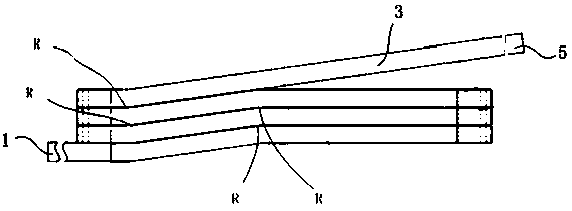
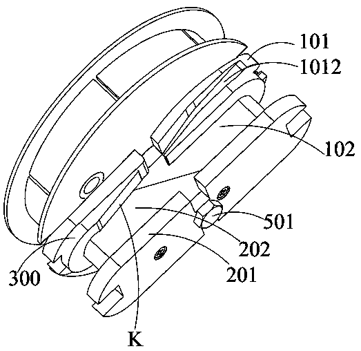
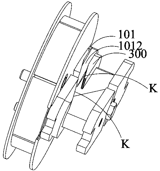
[0052] see Figure 1 to Figure 7 As shown, this embodiment provides a magnetic pole coil winding mold, which is suitable for such as figure 1 As shown in the magnetic pole coil, the magnetic pole coil is formed with a forward winding part and a reverse winding part of the electromagnetic wire during the winding process of the electromagnetic wire, and the lead-out line 1 of the forward winding electromagnetic wire and the reverse winding The lead-out lines 5 of the electromagnetic wires are drawn from the outside of the electromagnetic coil formed by winding (the forward winding and reverse winding here specifically refer to the opposite winding direction relative to the mold, and one of the directions is defined as Forward, and the other direction is reverse, the detailed definition of forward winding and reverse winding here can refer to the attached pole coil of DC motor with the patent publication number CN109728669A and its winding method).

[0053] Specifically, the mag...

Embodiment 2

[0069] On the basis of the magnetic pole coil winding die of Embodiment 1, this embodiment provides a winding method, using the magnetic pole coil winding die of Embodiment 1; specifically, the winding method of this embodiment includes:

[0070] Step S1: After the rear mold and the front mold are locked to the unwinding disk, wind the unwinding magnet wire 3 reserved for the magnet wire on the unwinding disk.

[0071] Specifically, step S1 includes:

[0072] Step S11, determine the length of the unwinding magnet wire 3 reserved for the magnet wire according to the calculated total length of the unwinding turns of the coil, and then determine the required length of the unwinding magnet wire 3 on the unwinding disk according to the length of the unwinding magnet wire 3 reserved for the magnet wire. The number of winding turns is adjusted by the fixed slot 4031 on the unwinding disc for fixing the start of the electromagnetic wire to adjust the length of the non-integer number o...


PUM


Abstract

The present invention discloses a winding mold of a magnetic pole coil and a winding method using the same. The winding mold of the magnetic pole coil comprises a rear mold, a front mold, an unwindingclamping plate set and an unwinding disc. The rear mold comprises a rear mold stop plate and a wedge rear mold core that are conjointly molded; the front mold comprises a front mold stop plate and awedge front mold core that are conjointly molded; an inclined surface of the wedge rear mold core is suitable to fit with an inclined surface of the wedge front mold core so that the wedge rear mold core and the wedge front mold core are spliced into a winding mold core suitable for electromagnetic wire winding; the front mold stop plate is distributed opposite to the rear mold stop plate and a section is formed between the rear mold stop plate and the front mold stop plate for splicing the wedge front mold core and the wedge front mold core; and the unwinding clamping plate set comprises a pair of turn clamping plates that are oppositely arranged. By using the winding mold of the magnetic pole coil and the winding method using the winding mold in the present invention, the compactness ofthe magnetic pole coil can be improved after winding.

Description

technical field [0001] The invention relates to the technical field of motor manufacturing and processing, in particular to a magnetic pole coil winding die and a winding method using the magnetic pole coil winding die. Background technique [0002] In power equipment such as DC motors, AC synchronous motors and transformers, magnetic pole coils are important components. With the increase in power density of electrical equipment such as motors, the structure of magnetic pole coils is also required to be more compact and the current density increased. For forming the magnetic pole coil, the winding mold fixed on it is usually driven by the motor or the spindle of the machine tool to rotate, the wire is wound on the winding mold and then demoulded to complete the coil production. [0003] For example, the patent of Publication No. CN108573809A "A Winding Die Component and Its Winding Die" discloses a winding die assembly, which includes a transmission structure and a winding d...

Claims


Application Information

Patent Timeline
Patent Type & Authority Patents(China)
IPC IPC(8): H02K15/04H01F41/06
CPCH01F41/06H02K15/045
Inventor 曹扬范勇姜敞陈锋吴军徐建洪卢念成
Owner NEW UNITED RAIL TRANSIT TECH
Why Eureka
Try Eureka