Transmitter drive circuit and method
A driving circuit and transmitter technology, applied in the direction of TV, electrical components, color TV, etc., can solve the problems of large fluctuation of driver output current and large fluctuation of impedance matching resistance, so as to facilitate on-chip integration, reduce negative effects, and improve The effect of the impedance matching effect
- Summary
- Abstract
- Description
- Claims
- Application Information
AI Technical Summary
Problems solved by technology
Method used
Image
Examples
Embodiment 1
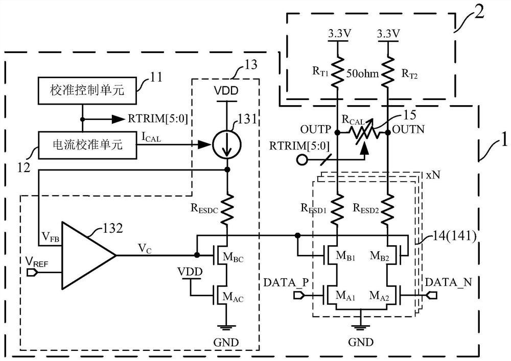
[0084] Such as figure 1 As shown, this embodiment provides a sending end driving circuit 1, and the sending end driving circuit 1 includes:
[0085] Calibration control unit 11 , current calibration unit 12 , bias voltage generation unit 13 , output stage drive unit 14 and impedance matching unit 15 .
[0086] Such as figure 1 As shown, the calibration control unit 11 is used to generate a calibration control signal RTRIM[5:0] that varies with changes in process, power supply voltage and temperature.
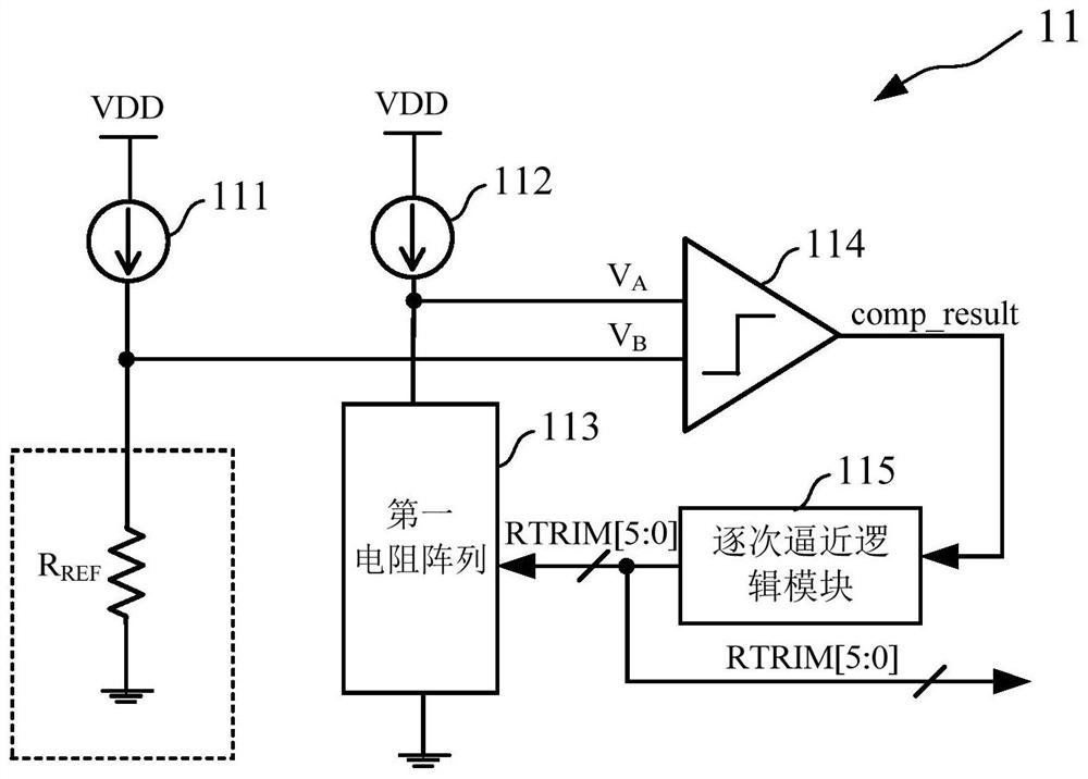
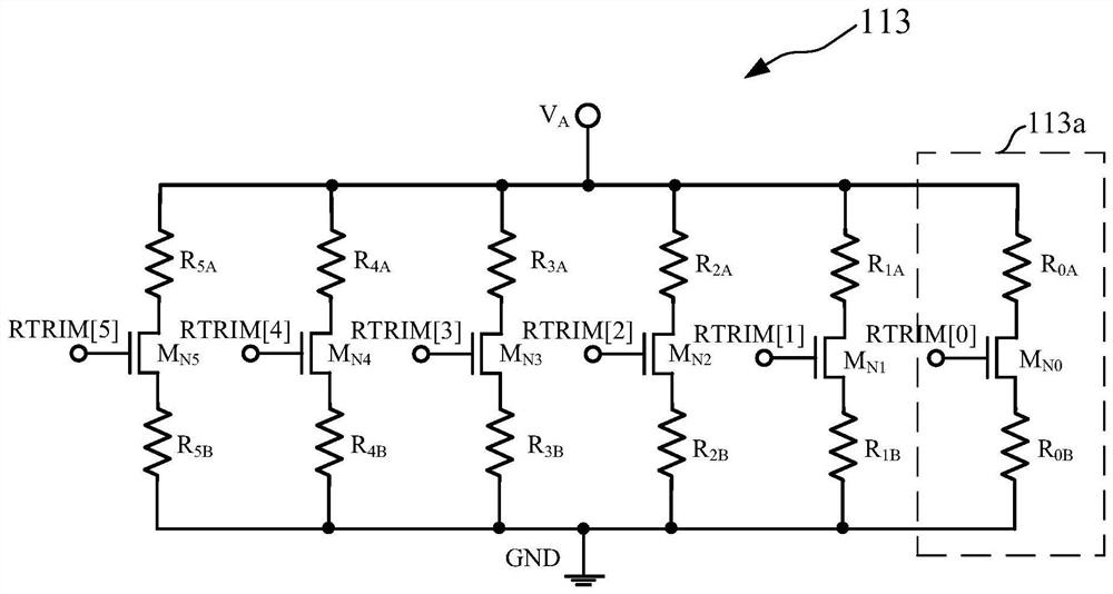
[0087] Specifically, the calibration control unit 11 gradually adjusts the resistance value of the built-in first resistor array approaching the external reference resistor gradually based on the successive approximation method, and finally the two keep the same, and sends the control signal of the first resistor array to output as the calibration control signal RTRIM[5:0]. In this embodiment, the calibration control signal is a 6-bit control bus signal, and the number of bit...
PUM
 Abstract
Description
Claims
Application Information
 - R&D
- Intellectual Property
- Life Sciences
- Materials
- Tech Scout
- Unparalleled Data Quality
- Higher Quality Content
- 60% Fewer Hallucinations
Browse by: Latest US Patents, China's latest patents, Technical Efficacy Thesaurus, Application Domain, Technology Topic, Popular Technical Reports.
© 2025 PatSnap. All rights reserved.Legal|Privacy policy|Modern Slavery Act Transparency Statement|Sitemap|About US| Contact US: help@patsnap.com


