Side plate structure of novel drawer slide rail

A side panel and drawer technology, which is applied to drawers, furniture parts, household appliances, etc., can solve the problems of scrapping the overall structure of the side panel, complex shell structure, structural damage, etc., to save material costs, reduce overall weight, and improve service life. Effect

Pending Publication Date: 2019-05-10
DONGGUAN GERUISI PRECISION HARDWARE TECH CO LTD
View PDF7 Cites 0 Cited by
  • Summary
  • Abstract
  • Description
  • Claims
  • Application Information

AI Technical Summary

Problems solved by technology

[0003] In the above-mentioned patent, the part where the side plate shell is connected to the supporting upper rail needs to be provided with steps and part of the plate body to connect the shell with the supporting upper rail through fasteners or riveting. Such a structure not only makes the structure of the shell too complicated and difficult to manufacture , and there is a step part with a right-angle structure, which will cause a large stress concentration on the shell, and long-term use will easily cause structural damage at this place and lead to the scrapping of the overall structure of the side plate

Method used


Image

  • Side plate structure of novel drawer slide rail
  • Side plate structure of novel drawer slide rail
  • Side plate structure of novel drawer slide rail

Examples


Embodiment 1

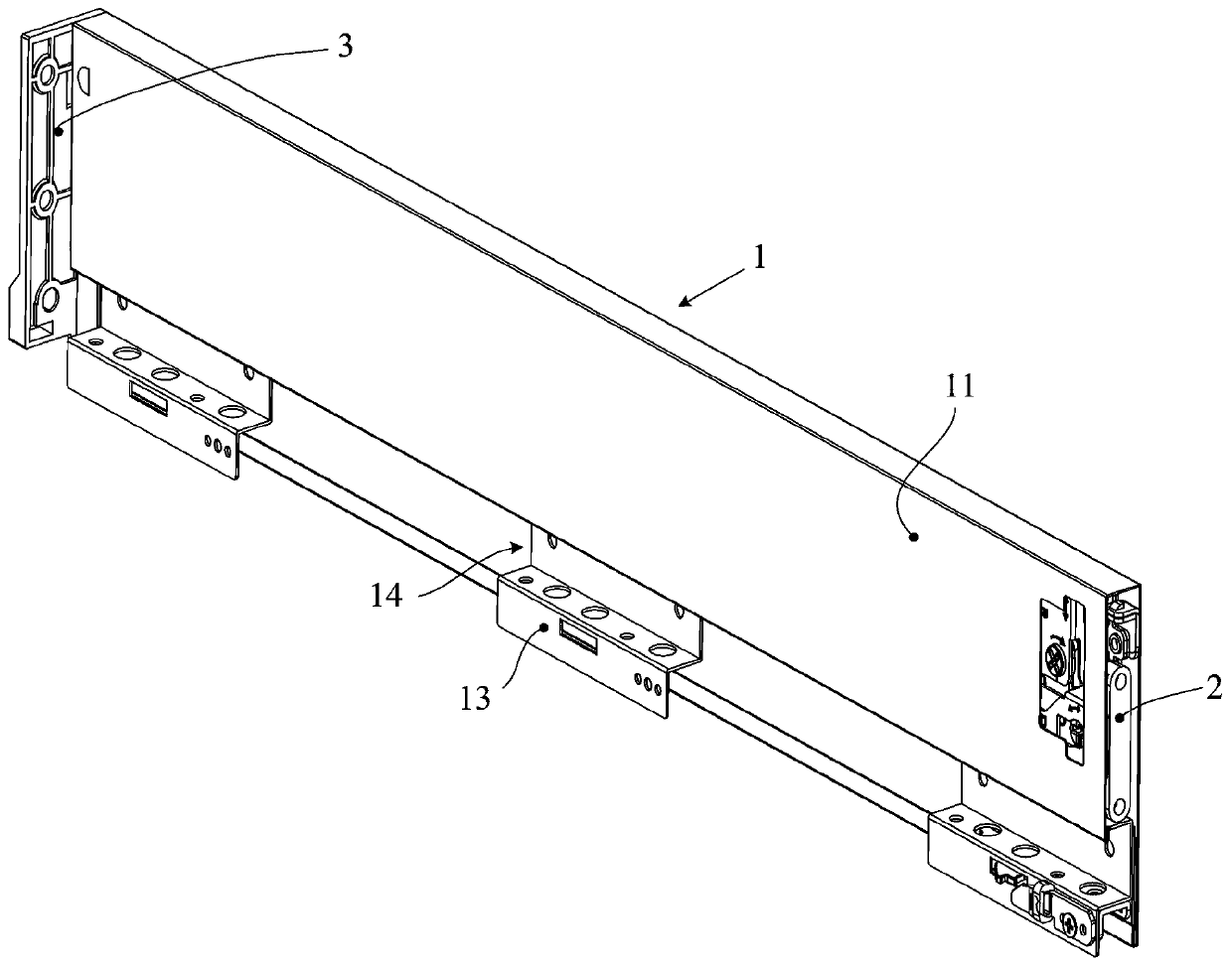
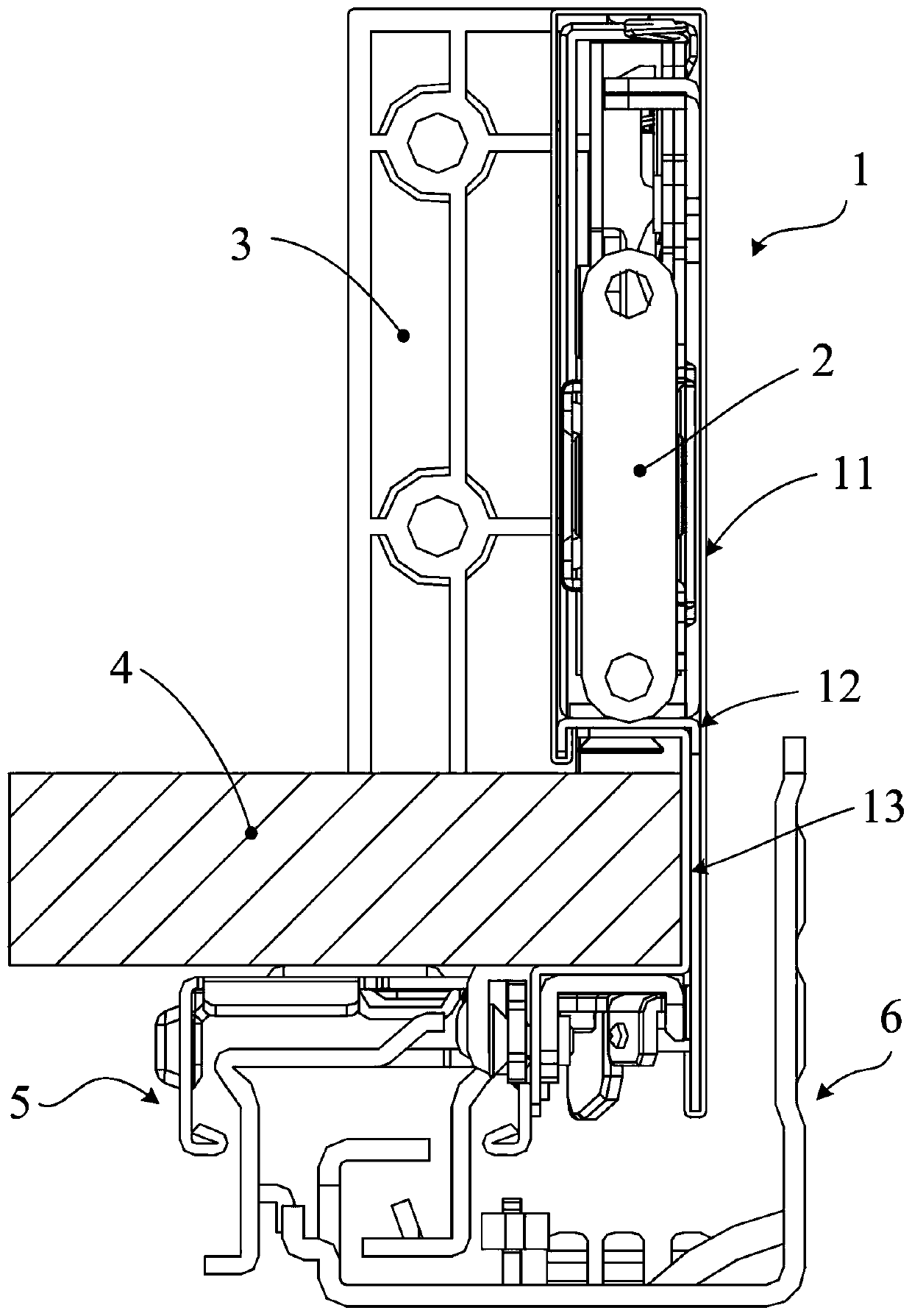
[0034] See Figure 1 to Figure 6 The side plate structure of the novel drawer slide rail of the embodiment of the present invention includes a side plate 1 arranged along the drawer pulling direction, the front part of the side plate 1 is provided with a front connecting piece 2 connected with the front panel, and the rear part of the side plate is provided with a rear The connector 3 is connected to the back panel, and the side panel 1 of this embodiment is composed of a side panel shell 11, an upper side panel frame 12 and a lower side panel frame 13, and the lower part of the side panel shell 11 is at least provided with an inward bending portion and an upper side panel. The bending part of the plate frame 12 is connected by plugging. The lower side plate frame 13 is provided with at least one horizontal part and the upper side frame 12 to form the installation groove 14 for installing the drawer bottom plate 4. The lower side plate frame 13 and the movable slide rail of the...

Embodiment 2

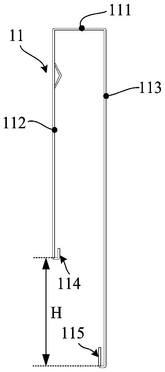
[0041] See Figure 7 , The present embodiment has the following distinguishing technical features from Embodiment 1: elastic members 125 are provided on the concave bottom surface of the first inner curved portion 114 and the concave bottom surface of the second inner curved portion 115. Preferably, the elastic member 125 of this embodiment can be a wedge-shaped block, and the ends of the first vertical support portion 122 and the second vertical support portion 123 are provided with an inclined portion 124 to cooperate with the wedge-shaped block, and the inclined portion and the wedge-shaped The elastic parts of the block are misplaced and matched with each other, so that the mutual cooperation between the vertical support part and the inner bending part is not easy to loosen, and the elastic part is set, and the elastic deformation of the elastic part can compensate the side plate shell and the upper side plate frame. Due to manufacturing errors, when the two are matched, i...


PUM


Abstract

The invention discloses a side plate structure of a novel drawer slide rail. The side plate structure comprises a slide plate arranged along the drawing direction of a drawer, wherein a front connecting component is arranged at the front part of the side plate and is connected with a front panel, a rear connecting component is arranged at the rear part of the side plate and is connected with a rear back plate; the side plate is formed by connecting a slide plate shell, an upper side plate frame and a lower side plate frame; an inner bending part is at least arranged at the lower part of the side plate shell and is connected with the bending part of the upper side plate frame through insertion, a horizontal part is at least arranged at the lower side plate frame to form a mounting slot formounting a drawer base plate with the upper side plate frame, and the lower side plate frame is detachably connected with a movable slide rail of the slide rail. Compared with the prior art, the technical scheme of the invention has the advantages of reliable structure, safety in use and the like, the use reliability of the side plate structure of the drawer can be effectively improved, the structure is simplified, and the production cost is lowered.

Description

technical field [0001] The invention relates to the technical field of drawer sliding devices, in particular to a side plate structure of a novel drawer slide rail. Background technique [0002] Chinese patent (authorized notification number CN103431656B) discloses a metal side panel structure for a drawer. The side panel of this patent is formed by three steel profiles, including a side panel shell, a supporting upper rail and a supporting lower rail, and the supporting upper rail and The supporting lower rail is fixed as a whole, the thickness of the side plate shell is smaller than the width of the moving sliding rail of the sliding rail assembly, and the inner wall is at least partly vertical, and at least one bending part is provided outwardly to support the upper rail and / or support the lower rail connect. [0003] In the above-mentioned patent, the part where the side plate shell is connected to the supporting upper rail needs to be provided with steps and part of th...

Claims


Application Information

Patent Timeline
Patent Type & Authority Applications(China)
IPC IPC(8): A47B88/90
Inventor 罗志明
Owner DONGGUAN GERUISI PRECISION HARDWARE TECH CO LTD
Why Eureka
Try Eureka