
Low-noise food processor

A food processing machine, low-noise technology, applied in the field of food processing, can solve the problems of large noise on the countertop, direct downward airflow, easy impact of airflow, etc., to achieve the effect of avoiding noise, avoiding backflow and counterflow of airflow, and accelerating airflow circulation

Active Publication Date: 2019-05-10
JOYOUNG CO LTD
View PDF11 Cites 2 Cited by
  • Summary
  • Abstract
  • Description
  • Claims
  • Application Information

AI Technical Summary

Problems solved by technology

[0002] Existing food processing machines usually include a machine base and a stirring cup, and a motor is arranged in the machine base to drive the pulverizer in the stirring cup to process the food in the stirring cup, and the motor will continue to generate heat during the working process, so the current Some food processing machines are generally equipped with a heat dissipation structure, through which the cavity defined by the base can be radiated heat. However, the air outlet of this heat dissipation mechanism is directly downward, so the airflow is easy to hit the table and generate large noise

Method used


Image

  • Low-noise food processor
  • Low-noise food processor
  • Low-noise food processor

Examples


Embodiment 1

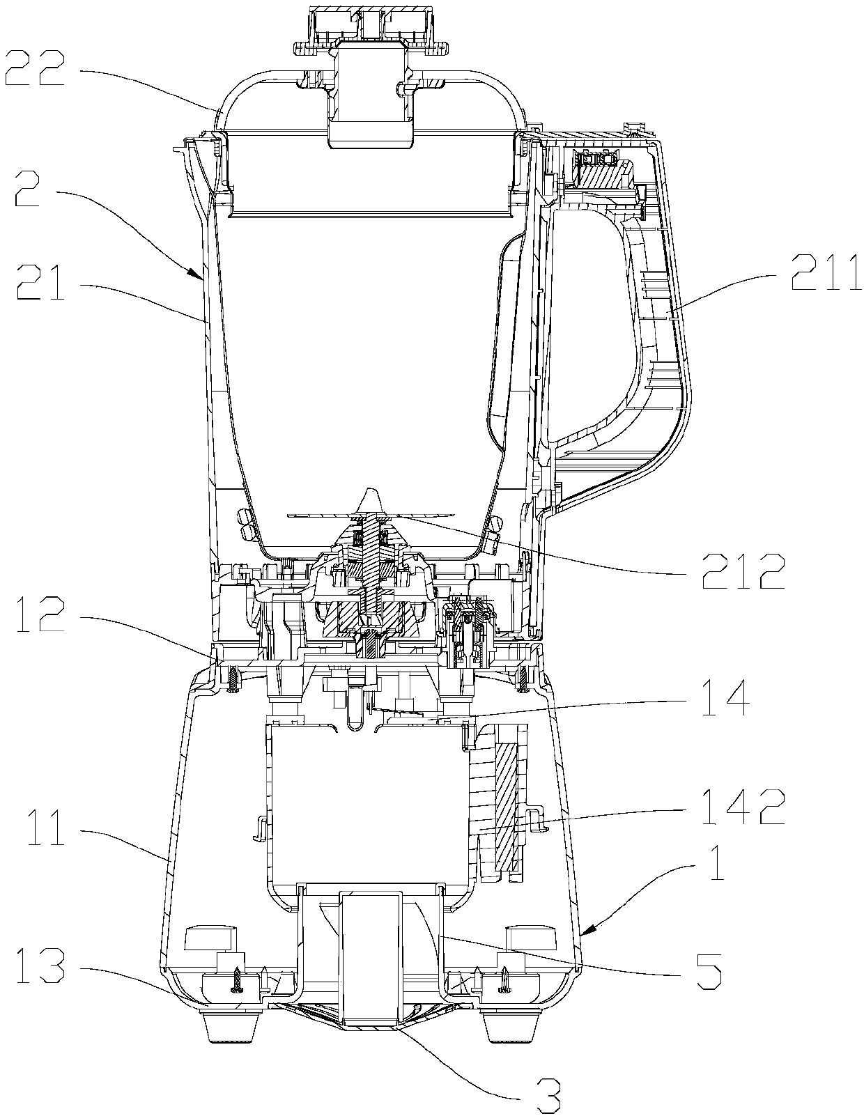
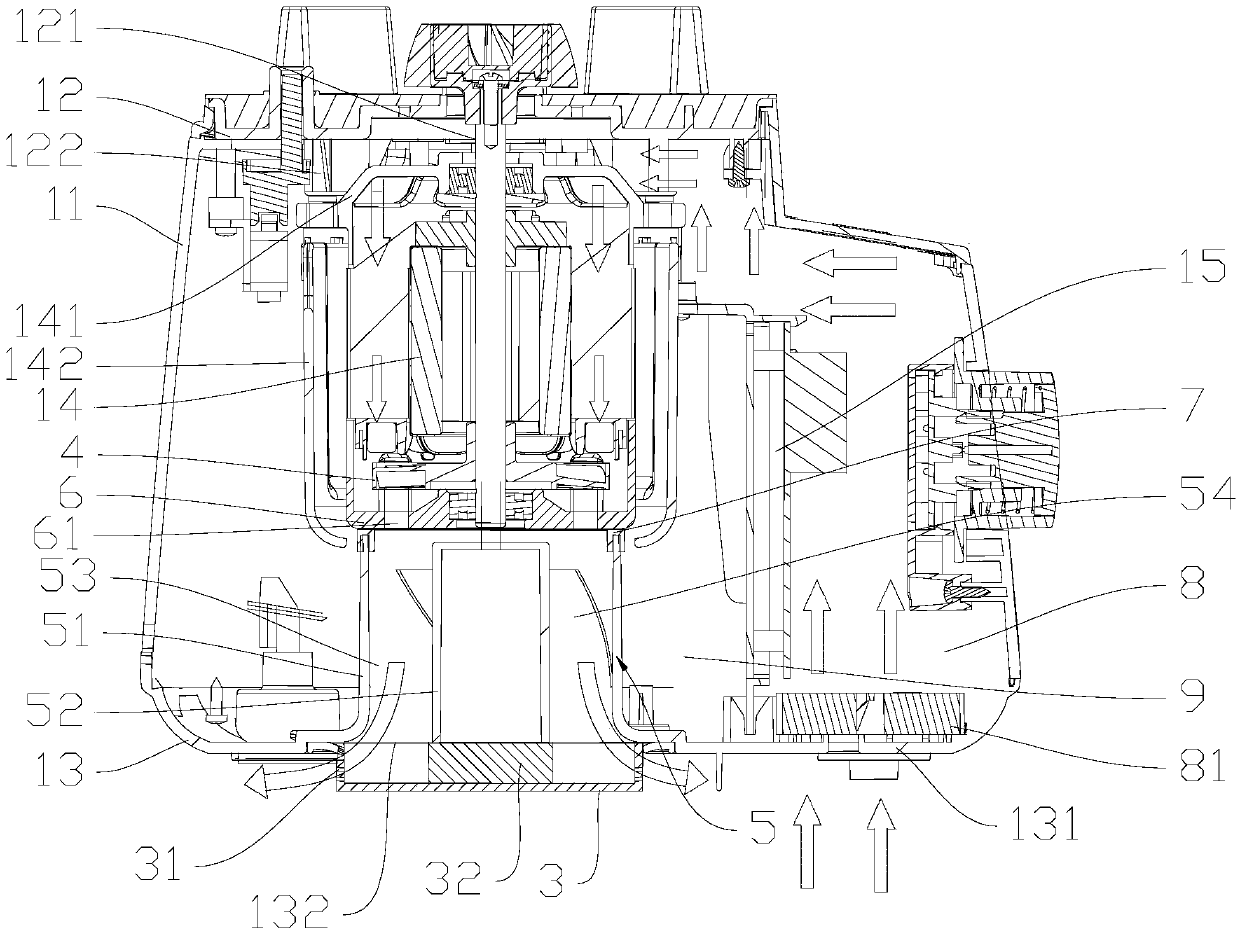
[0035] like figure 1 and figure 2As shown, the food processor of this embodiment includes a machine base 1 and a stirring cup 2 connected to the machine base 1. The machine base 1 includes a casing 11, a top cover 12 and a bottom cover 13, and the top cover 12 and the bottom cover 13 are respectively Located on the top and bottom of the casing 11, the base 1 is provided with a motor 14 and a circuit board 15, the motor 14 and the circuit board 15 are located in the casing 11, the stirring cup 2 includes a cup body 21 and a cup cover 22, the cup body 21 It is a glass cup with a handle 211, and the cup cover 22 is a plastic cup cover. The cup cover 22 and the cup body 21 are enclosed to form a crushing space. The cup body 21 is provided with a crushing knife 212. connection, the two are connected by a coupling, the coupling includes an upper coupling and a lower coupling, the upper coupling is connected with the cutter shaft of the crushing knife 212, and the lower coupling is...

Embodiment 2

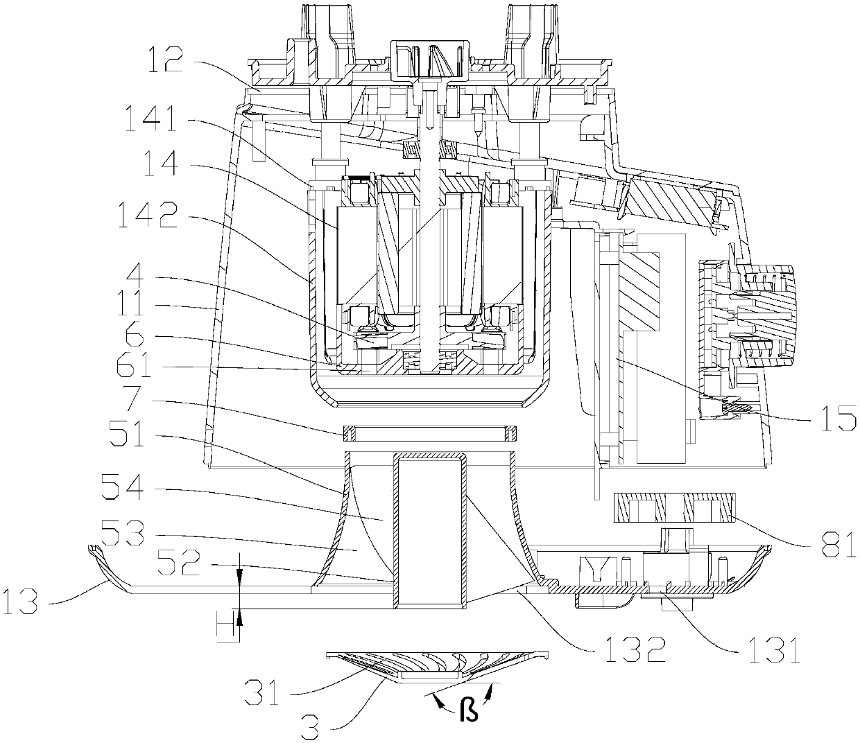
[0043] The difference between this embodiment and Embodiment 1 lies in the structure of the air duct and the exhaust hood, combined with Figure 3 to Figure 5 As shown, the connection between the first annular wall 51 of the air guide tube 5 and the bottom cover 13 has a radian α, that is, the connection between the lower end of the first annular wall 51 and the bottom cover 13 has a radian α, wherein 5°≤α≤ 35°. In this embodiment, α is 15°, which can guide the airflow out of the air guide tube 5 to the side, thereby avoiding the noise and airflow backflow caused by most of the airflow directly hitting the table surface directly, so that the ventilation of the machine base 1 is very good. smooth. The lower end of the first annular wall 51 extends outward to form a cylinder seat 511, which is located above the air outlet 132 and fixed on the bottom cover 13 by screws, and the first annular wall 51 is installed on the bottom cover 13 through the cylinder seat 511 Above all, thi...

Embodiment 3

[0056] The difference between this embodiment and Embodiment 1 and Embodiment 2 lies in the installation structure of the motor, combined with Figure 6 and Figure 7 As shown, the upper end of the motor 14 is provided with a motor bracket 141, and the motor 14 is fixedly arranged under the top cover 12 through the motor bracket 141. There is a distance A between the motor bracket 141 and the top cover 12, wherein 10mm≤A≤30mm, the distance A Form a communication channel connecting the top of the air inlet chamber 8 with the top of the exhaust chamber 9. In this embodiment, A is 18mm, which can effectively ensure that the airflow flowing through the air inlet chamber 8 passes through the motor from top to bottom to dissipate heat from the motor , the bottom cover 13 is provided with a bracket, the bracket is located below the motor 14 and abuts against the lower end of the motor 14. In this way, the upper and lower ends of the motor 14 are set to support and limit, which can ensu...


PUM


Abstract

The invention discloses a low-noise food processor, comprising a machine base with a motor and a circuit board, an agitating cup connected with the machine base, and a smashing cutter arranged in theagitating cup, wherein the machine base comprises a housing, a top cover and a bottom cover; an air inlet and an air discharge hole are formed in the bottom cover; the motor is located in the housing,the upper end of the motor shaft of the motor is connected with the smashing cutter, an exhaust fan is arranged at the lower end of the motor shaft, an exhaust hood is arranged at the air discharge hole, the exhaust hood comprises a bottom wall and a side wall, exhaust holes are formed in the side wall of the exhaust hood, an air guide cylinder is arranged on the bottom cover, the air guide cylinder comprises a first annular wall and a second annular wall which are arranged from outside to inside, the upper end of the first annular wall is arranged at the outer periphery of the exhaust fan ina covering manner, the lower end of the first annular wall is communicated with the air discharge hole, the upper end hole of the second annular wall is sealed, an annular air guide passage is formedbetween the first annular wall and the second annular wall, and an air guide plate is arranged in the annular air guide passage. According to the technical scheme of the invention, noise caused by direct frontage impact of air flow to the table board can be avoided.

Description

technical field [0001] The invention belongs to the field of food processing, in particular to a low-noise food processing machine. Background technique [0002] Existing food processing machines usually include a machine base and a stirring cup, and a motor is arranged in the machine base to drive the pulverizer in the stirring cup to process the food in the stirring cup, and the motor will continue to generate heat during the working process, so the current Some food processing machines are generally equipped with a heat dissipation structure, through which the cavity defined by the base can be radiated heat. However, the air outlet of this heat dissipation mechanism is directly downward, so the airflow is easy to hit the table and generate large noise. Contents of the invention [0003] The object of the present invention is to provide a low-noise food processing machine. [0004] In order to solve the above technical problems, the present invention provides a low-noi...

Claims


Application Information

Patent Timeline
IPC IPC(8): A47J43/046A47J43/07
Inventor 王旭宁金剑刘义军黄东仁
Owner JOYOUNG CO LTD
Learn More