AI technical title is built by PatSnap AI team. It summarizes the technical point description of the patent document.
A chip and spacer technology, applied in the field of chip pulling device, can solve the problems of manual pulling, effort, chip damage, etc., and achieve the effect of easy operation, simple structure and easy realization
Active Publication Date: 2020-11-20
亳州易泽信息科技有限公司
View PDF2 Cites 0 Cited by
Summary
Abstract
Description
Claims
Application Information
AI Technical Summary
This helps you quickly interpret patents by identifying the three key elements:
Problems solved by technology
Method used
Benefits of technology
Problems solved by technology
However, the claws used in this kind of puller are likely to be pointed, which is easy to cause damage to the chip, and it needs to be pulled out manually, which is laborious.
Method used
Image
Click on the blue label to locate the original text in one second.
Reading with bidirectional positioning of images and text.
Examples
Embodiment 1
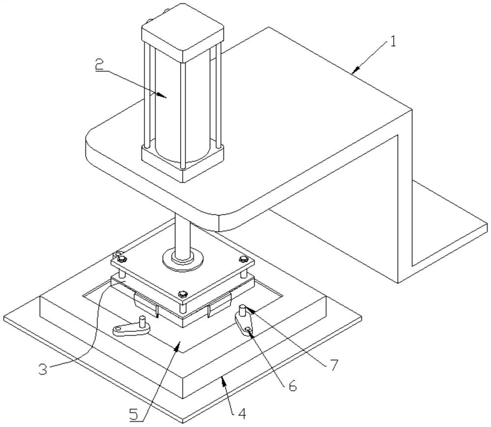
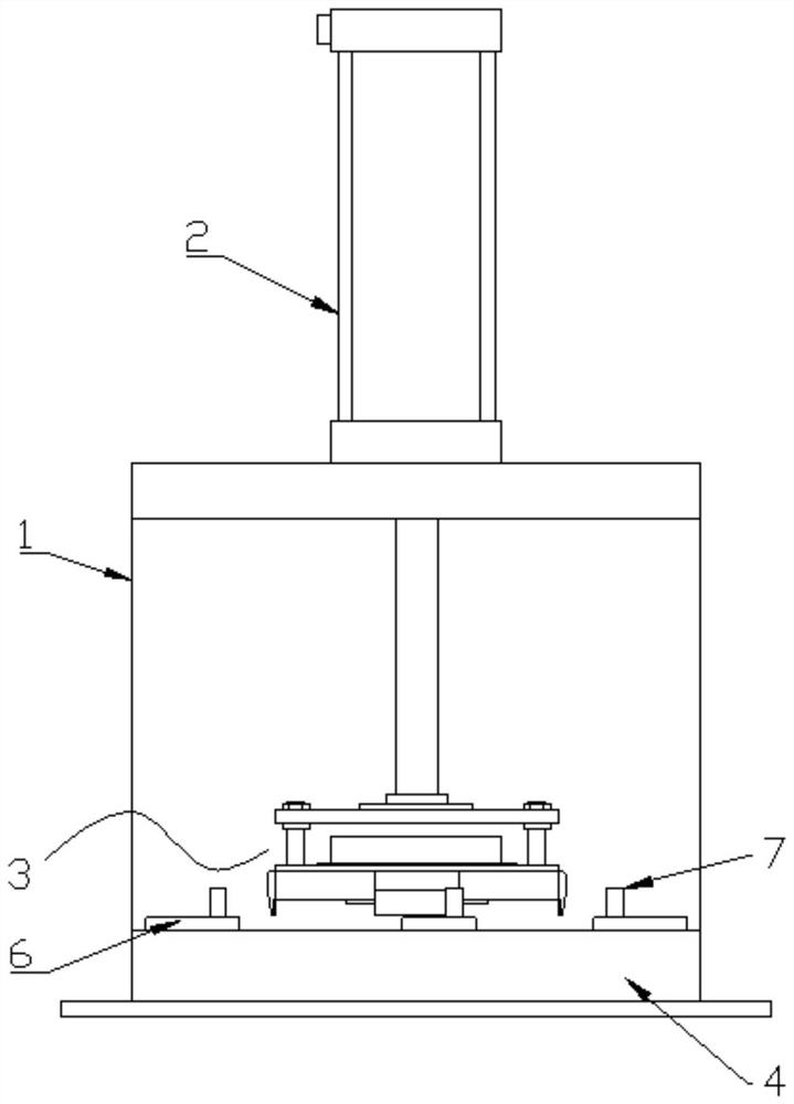
[0033] Such as Figure 1 to Figure 6 As shown, a chip lifting device includes a support 1, an actuator 2, a grabbing mechanism 3 and a chip placement table 4;
[0034] The actuator 2 is installed on the support 1, and the support 1 is provided with reinforcing ribs 13, and the lower end of the actuator 2 is connected to the grasping mechanism 3 and drives the grasping mechanism 3 to move up and down;
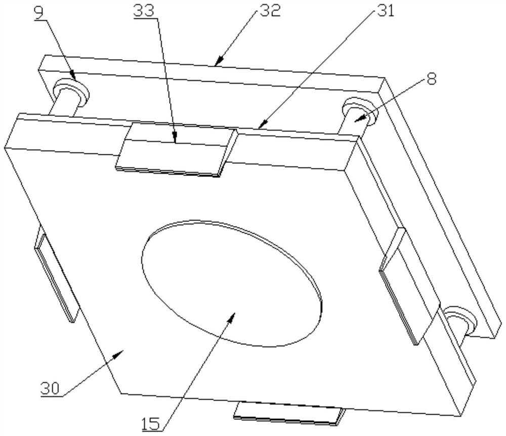
[0035] The grasping mechanism 3 is used to grasp the chip and pull out the chip by means of the actuator 2, which specifically includes a base 30, a cover plate 31, a connecting plate 32, claws 33, a connecting rod 34, a turntable 35, Worm wheel 36, worm screw 37 and rotary drive motor 38, described base 30 is provided with four guide grooves 39 and the angle between two adjacent guide grooves 39 is 90 degrees, guide block 310 is slidably connected in guide groove 39 , the outer end of the guide block 310 is connected to the claw 33, the inner end of the guide block 310 is hing...
Embodiment 2
[0041] Such as Figure 7 to Figure 9 As shown, a chip lifting device includes a support 1, an actuator 2, a grabbing mechanism 3 and a chip placement table 4;
[0042] The actuator 2 is installed on the support 1, and the support 1 is provided with reinforcing ribs 13, and the lower end of the actuator 2 is connected to the grasping mechanism 3 and drives the grasping mechanism 3 to move up and down;
[0043] The grasping mechanism 3 is used to grasp the chip and pull out the chip by means of the actuator 2, which specifically includes a base 30, a cover plate 31, a connecting plate 32, claws 33, a connecting rod 34, a turntable 35, Worm wheel 36, worm screw 37 and rotary drive motor 38, described base 30 is provided with four guide grooves 39 and the angle between two adjacent guide grooves 39 is 90 degrees, guide block 310 is slidably connected in guide groove 39 , the outer end of the guide block 310 is connected to the claw 33, the inner end of the guide block 310 is hing...
PUM
Abstract
The invention discloses a chip drawing device and a use method thereof, and relates to the technical field of chip production and processing. The device comprises a supporting seat, a performing mechanism, a grabbing mechanism and a chip storing platform, wherein the performing mechanism is mounted on the supporting seat; the lower end of the performing mechanism is connected to the grabbing mechanism, and the grabbing mechanism is driven to move up and down through the performing mechanism; the grabbing mechanism is used for grabbing a chip and drawing the chip through the performing mechanism; the chip storing platform is positioned under the grabbing mechanism, and a chip storing groove is formed in the chip storing platform; and at least two compressing mechanisms for compressing a PCBA board are arranged on the chip storing platform at the outer side of the chip storing groove. According to the device, the chip can be clamped from the side surface through the grabbing mechanism and then is drawn through the performing mechanism; the whole process is simple to operate; a chip body and surrounding elements are prevented from damage; in addition, the device is simple in structure, and easy to realize.
Description
technical field [0001] The invention relates to the technical field of chip production and processing, in particular to a semi-automatic chip lifting device with simple structure and strong operability. Background technique [0002] In the field of electronic design, especially in the application field of single-chip microcomputer technology, when it is necessary to modify the program inside the single-chip microcomputer or to recycle chips on some old circuit boards, it is inevitable to encounter the situation of pulling out chips. Existing chip extraction is to use tools such as tweezers to forcibly pry the chip from the corner of the chip, but because this method uses force from the corner of one side of the chip, the force on the solder joints of each part of the chip is seriously uneven, and it is easy to dislodge the original chip. The position and structure of the original fracture surface of the solder joint are changed or covered. [0003] The Chinese Patent Public...
Claims
Application Information
Patent Timeline
Application Date:The date an application was filed.
Publication Date:The date a patent or application was officially published.
First Publication Date:The earliest publication date of a patent with the same application number.
Issue Date:Publication date of the patent grant document.
PCT Entry Date:The Entry date of PCT National Phase.
Estimated Expiry Date:The statutory expiry date of a patent right according to the Patent Law, and it is the longest term of protection that the patent right can achieve without the termination of the patent right due to other reasons(Term extension factor has been taken into account ).
Invalid Date:Actual expiry date is based on effective date or publication date of legal transaction data of invalid patent.

