Spatial geometric error measurement and identification method for multi-line machine tools based on laser interferometer

A technology of laser interferometer and geometric error, applied in measuring/indicating equipment, metal processing machinery parts, metal processing equipment, etc., can solve problems such as coefficient matrix singularity, limited error identification, difficult to solve production problems, etc.

Active Publication Date: 2019-05-10
无锡超通智能制造技术研究院有限公司
View PDF7 Cites 10 Cited by
  • Summary
  • Abstract
  • Description
  • Claims
  • Application Information

AI Technical Summary

Problems solved by technology

For spatial geometric errors, its compensation technology is mainly limited by error identification. At present, the main methods used are single error measurement and spatial geometric error identification; single error measurement has low efficiency, requires many instruments, and is difficult to measure, making it difficult to solve production problems. ; The spatial geometric error identification method obtains various geometric error values ​​by measuring the required information and using the spatial error model identification, and then realizes the compensation of the spatial geometric error
[0004] Scholars at home and abroad have done a lot of research work on the comprehensive measurement and identification methods of geometric errors of laser interferomete

Method used


Image

  • Spatial geometric error measurement and identification method for multi-line machine tools based on laser interferometer
  • Spatial geometric error measurement and identification method for multi-line machine tools based on laser interferometer
  • Spatial geometric error measurement and identification method for multi-line machine tools based on laser interferometer

Examples


Embodiment Construction

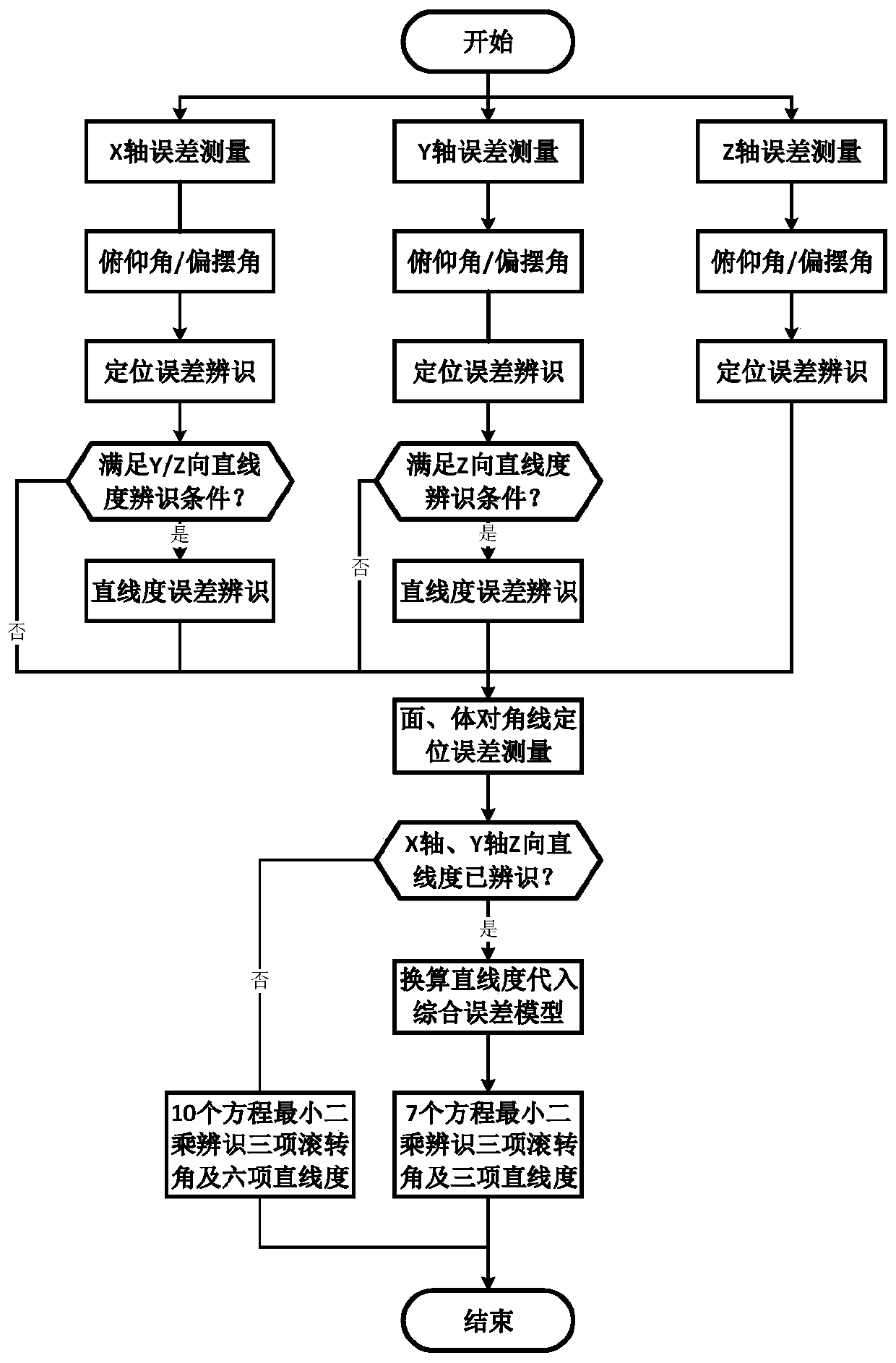
[0057] The present invention will be described in further detail in conjunction with the accompanying drawings.

[0058] refer to figure 1 , a method for measuring and identifying spatial geometric errors of multi-line machine tools based on laser interferometers, including the following steps:

[0059] 1) Plan the measurement space in the machine tool stroke space, and design and plan the measurement path in the measurement space;

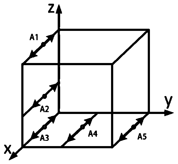
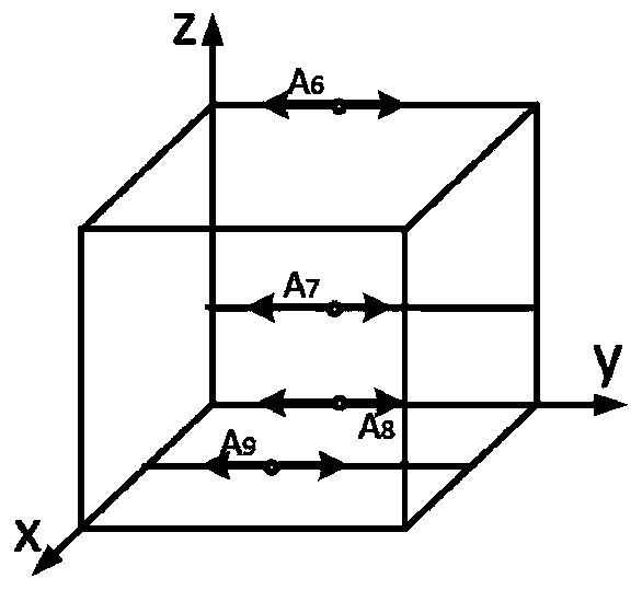
[0060] For the X axis, refer to figure 2 , in the measurement space, the positioning error, two non-roll angle errors and two mutually perpendicular straightness errors are measured. The positions of the measurement lines are all parallel to the X axis, and the positioning error δ x (x) The measurement starting point is A 1 (x 1 ,y 1 ,z 1 ), around the Y-axis angle error ε y (x) Measurement starting point A 2 (x 2 ,y 2 ,z 2 ), around the Z-axis angle error ε z (x) Measurement starting point A 3 (x 3 ,y 3 ,z 3 ), Y-direction straig...


PUM


Abstract

The invention discloses a spatial geometric error measurement and identification method for multi-line machine tools based on a laser interferometer. The method includes steps of (1), planning a measurement space and a measurement path in a machine travel space; (2), measuring a positioning error of the X-axis, two non-rolling angle errors, and two straightness errors; (3), measuring a positioningerror of the Y-axis, the two non-rolling angle errors, and a Z-direction straightness error; (4), measuring a positioning error of the Z-axis and the two non-rolling angle errors; and (5), identifying the straightness error when the measurement conditions are met, measuring the positioning error on the face diagonal and the body diagonal, and identifying by combing a spatial comprehensive error model to obtain the error of the roll angle and three straightness errors including verticality errors; and if no straightness errors are identified before, identifying by combining with a straightnesserror formula to obtain three errors of the roll angle and six straightness errors. According to the method, identification requirements of the spatial geometric errors are met, and the measurement efficiency and measurement accuracy are high.

Description

technical field [0001] The invention belongs to the technical field of machining accuracy of numerical control machine tools, and in particular relates to a method for measuring and identifying spatial geometric errors of multi-line machine tools based on laser interferometers. Background technique [0002] Error factors such as geometric error and thermal error in the machining process seriously affect the machining accuracy of the machine tool. Among them, geometric error and thermal error account for 40% to 70% of the total error. Therefore, solving geometric error is the key to improving the accuracy of CNC machine tools technology is of great importance. Geometric errors are mainly caused by the shape and position accuracy of the CNC machine tool parts themselves and the assembly errors generated during the assembly process, and are reflected on the moving parts with the movement of the machine tool, thereby affecting the machining accuracy of the machine tool. Geometr...

Claims


Application Information

Patent Timeline
IPC IPC(8): B23Q17/00B23Q17/24
Inventor 陶涛殷成明陈海博梅雪松姜歌东许睦旬
Owner 无锡超通智能制造技术研究院有限公司
Why Eureka
Try Eureka