A Method for Determining the Counterpoint Position of Vertical Axis Feed System of CNC Machine Tool

A technology of feed system and CNC machine tool, which is applied in the direction of metal processing machinery parts, metal processing equipment, measuring/indicating equipment, etc. Flutter and other issues

Active Publication Date: 2020-03-31
XI AN JIAOTONG UNIV
View PDF4 Cites 0 Cited by
  • Summary
  • Abstract
  • Description
  • Claims
  • Application Information

AI Technical Summary

Problems solved by technology

The size of the overturning moment will directly affect the normal / tangential force state of the guide rail slider pair that constrains the moving parts, and then affect the contact stiffness of the guide rail slider pair dynamic joint, and finally affect the modal frequency distribution of the system. Therefore, the Its modal frequency is regarded as an ideal value to select high-precision and efficient processing parameters, otherwise it may cause processing chatter and other phenomena, which will affect the processing quality of parts
[0004] For the determination of the position of the counterpoint of the vertical axis feed system of a CNC machine tool with a counterweight system, design engineers mostly determine it based on their own engineering experience and in combination with the physical space of the system, which leads to different engineers having different opinions on the position of the counterpoint of the system. There are often differences in the selection of the system, resulting in different modal frequency distributions of the system, which will eventually affect the processing quality of the parts

Method used


Image

  • A Method for Determining the Counterpoint Position of Vertical Axis Feed System of CNC Machine Tool
  • A Method for Determining the Counterpoint Position of Vertical Axis Feed System of CNC Machine Tool
  • A Method for Determining the Counterpoint Position of Vertical Axis Feed System of CNC Machine Tool

Examples


Embodiment Construction

[0042] The present invention will be further described in detail below in conjunction with specific embodiments, which are explanations of the present invention rather than limitations.

[0043] A method for determining the position of the counterpoint of the vertical axis feed system of a CNC machine tool according to the present invention can be actively determined at the beginning of the design, and it includes the following steps:

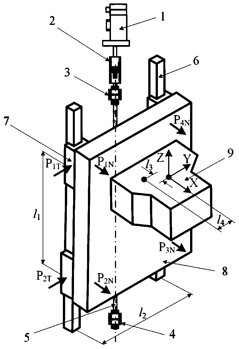
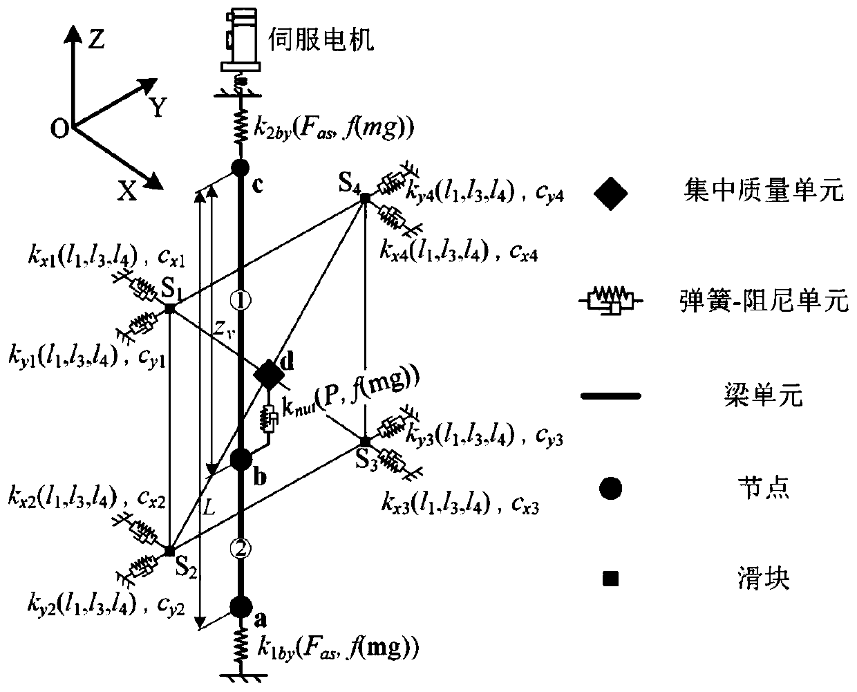
[0044]Step 1. For the vertical axis feed system of CNC machine tools with counterweight devices, use CAD software to obtain the center of mass position of the vertical moving parts through the established CAD model, and give the vertical axis feed system containing the center of mass position coordinate system of the moving parts. Give a schematic diagram of the system structure and a dimensional relationship diagram of the span between the two guide rails and the distance between the two sliders, such as figure 1 As shown; the position of the ...


PUM


Abstract

The invention provides a method for determining a counterweight point position of a vertical axis feeding system of a numerical control machine tool. Active design of the counterweight point positionis realized in the design stage of the vertical axis feeding system of the numerical control machine tool, so that the frequency of a vibration source of the system is avoided, and finally a theoretical foundation is provided for achieving high-precision high-efficiency cutting parameters. In the design initial stage of the vertical axis feeding system, a stress change interval of each guide railsliding block pair, an equivalent rigidity change interval of each guide rail sliding block pair and the modal frequency distribution rule of the corresponding vertical axis feeding system are given at different counterweight point positions, active design of the counterweight point position is realized, so that the theoretical foundation is provided for selecting proper main shaft rotating speed,cutting parameters and the like.

Description

technical field [0001] The invention relates to the technical field of design and manufacture of machine tool equipment, in particular to a method for determining the position of a counterpoint of a vertical axis feed system of a numerically controlled machine tool. Background technique [0002] A typical vertical machining center, as a working machine in the manufacturing industry, has been widely used in the manufacturing fields of ships, aerospace, and automobiles. [0003] For medium-sized and above machining centers, due to the high gravity of the moving parts, it is necessary to design a counterweight system to balance the gravity of the moving parts. However, it is difficult to design the position of the counterpoint at the center of mass of the moving part, which will cause the overturning moment of the moving part, and its value is related to the position of the counterpoint. The size of the overturning moment will directly affect the normal / tangential force state ...

Claims


Application Information

Patent Timeline
Patent Type & Authority Patents(China)
IPC IPC(8): B23Q17/22
Inventor 张会杰赵万华邹存范刘辉杨晓君吕盾张俊
Owner XI AN JIAOTONG UNIV
Why Eureka
Try Eureka