
Manufacturing method of optical fiber raw materials and special equipment for manufacturing optical fiber raw materials

A manufacturing method and technology of special equipment, applied to other household appliances, applications, optical components, etc., can solve the problems of different spacing between optical fiber filaments, lower production efficiency, uneven arrangement of optical fiber filaments, etc., to ensure the luminous effect, The swing range is large and the effect of ensuring straightness

Pending Publication Date: 2019-05-10
李发兰
View PDF20 Cites 0 Cited by
  • Summary
  • Abstract
  • Description
  • Claims
  • Application Information

AI Technical Summary

Problems solved by technology

However, this manufacturing method not only greatly increases the labor intensity of workers and reduces the manufacturing efficiency, but also manual operation will easily lead to different spacing between optical fiber filaments, non-uniform height of light-emitting points of optical fiber filaments, and uneven arrangement of optical fiber filaments, etc. etc., which makes the linear luminous effect of the optical fiber raw material poor, thereby affecting the luminous effect and decorative effect of the subsequent optical fiber crafts using the optical fiber raw material

Method used


Image

  • Manufacturing method of optical fiber raw materials and special equipment for manufacturing optical fiber raw materials
  • Manufacturing method of optical fiber raw materials and special equipment for manufacturing optical fiber raw materials
  • Manufacturing method of optical fiber raw materials and special equipment for manufacturing optical fiber raw materials

Examples


Embodiment

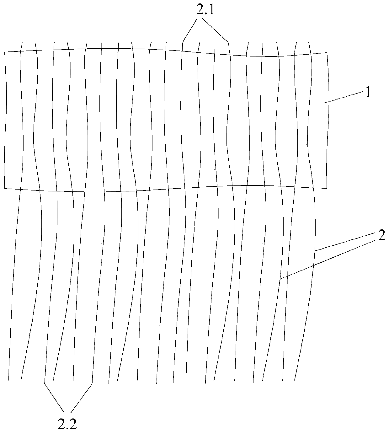
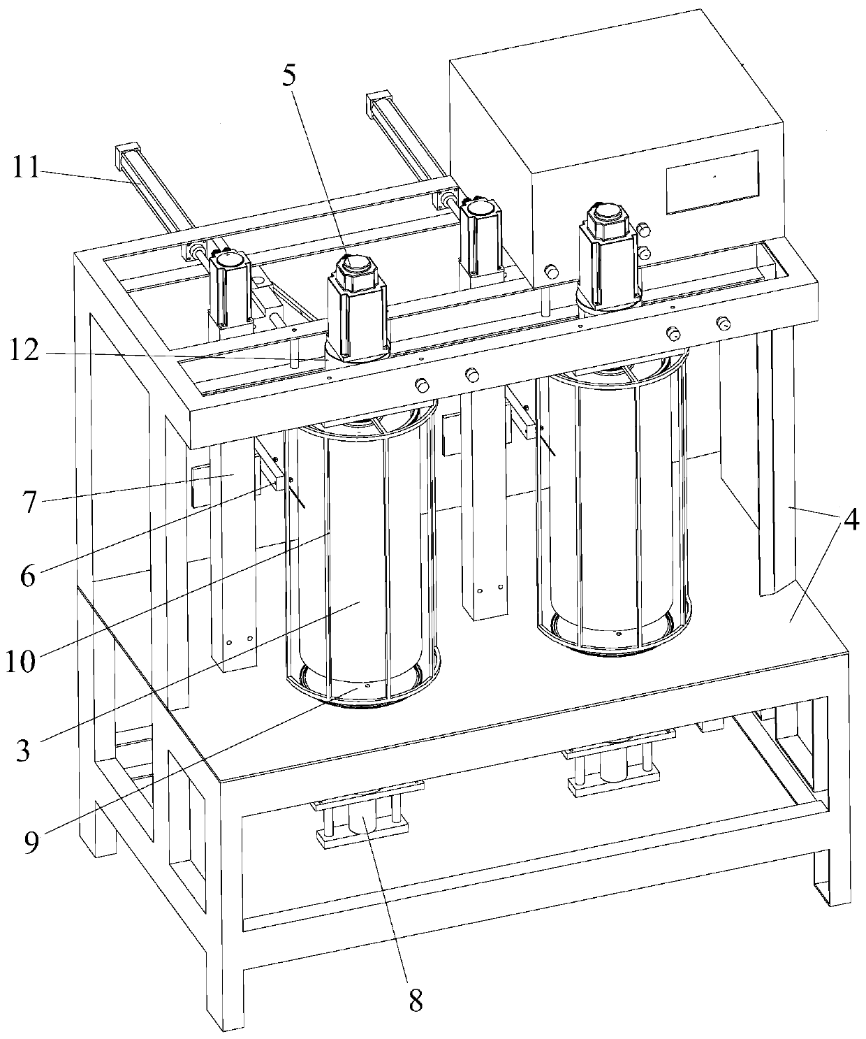
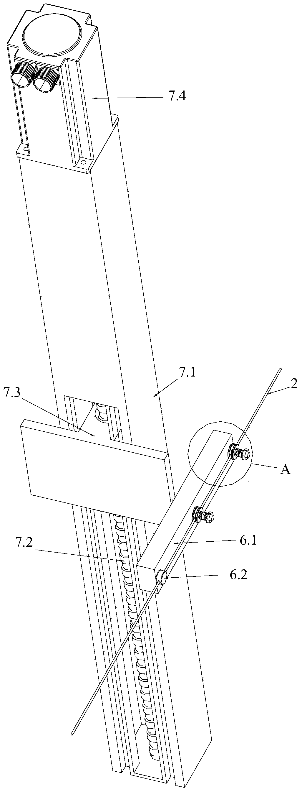
[0042] Such as Figure 1 to Figure 4 As shown, the manufacturing method of the optical fiber raw material of the present invention is as follows: the tube body 3 and the raw material base material 1 are arranged, the optical fiber filament 2 is wound on the tube body 3 to discharge the wire, and the raw material base material 1 is pasted on the tube body 3 for rowing. On the finished optical fiber 2, and cut the optical fiber 2; after cutting, one end of the optical fiber 2 pasted with the raw material substrate 1 is a light-emitting point, and forms a linear light-emitting end 2.1, and the other end is a light-introducing end 2.2. Compared with the light source, it realizes the manufacture of optical fiber raw materials. Specifically include the following steps:

[0043] In the first step, firstly, the tube body 3 and the raw material base material 1 are set and the density of the fiber optic filament 2 is set; then, the fiber optic filament 2 is wound on the tube body 3 wit...


PUM


Abstract

The invention provides a manufacturing method of optical fiber raw materials. Pipe bodies and raw material base materials are arranged, optical fiber wires are twined on the pipe bodies for wire arraying, the raw material base materials are adhered to the optical fiber wires after wire arraying is completed, on the pipe body, and the optical fiber wires are cut; and light-emitting points are arranged at one ends of the cut optical fiber wires to which the raw material base materials are adhered form a linear light-emitting end, and the other ends of the cut optical fiber wires are light ray leading-in ends, and are used for being opposite to a light source, so that the manufacturing of the optical fiber raw materials is realized. Through the adoption of the manufacturing method of the optical fiber raw materials disclosed by the invention, manual labor intensity can be reduced, and the production and manufacturing efficiency of an optical fiber light source can be improved; and besides, through the adoption of the manufacturing method of optical fiber raw materials, the optical fiber wires on the optical fiber raw materials can be uniformly arrayed in an unified manner, so that thelight-emitting effect, the decorating effect and the production quality of craftworks manufactured by the optical fiber raw materials can be guaranteed. The invention also provides special equipmentfor manufacturing the optical fiber raw materials, which is used for performing twining and wire arraying on the optical fiber wires. Through the adoption of the special equipment disclosed by the invention, quick, reliable and uniform wire arraying of the optical fiber wires can be realized.

Description

technical field [0001] The invention relates to the technical field of craft lighting ornaments, and more specifically, relates to a method for manufacturing optical fiber raw materials and special equipment thereof. Background technique [0002] With the development of the times and the advancement of technology, various lighting decorations have also been more and more widely used. Because lighting decorations are decorations with light and shadow effects, they use modern technology to add new charm to the technology of traditional decorations. [0003] Among them, because of their special visual effects, optical fiber handicrafts can beautify the home and surrounding environment, and are used to decorate the home and beautify the environment, and have always been loved by people. In existing handicrafts that use optical fiber as decoration, one end of the optical fiber is opposed to the light source, and the other end is used as a light-emitting point. [0004] Similar ...

Claims


Application Information

Patent Timeline
IPC IPC(8): B29C53/66B29C53/80B29L11/00
Inventor 李发兰
Owner 李发兰
Learn More