Sensor-based vehicle tire maintenance system and maintenance method thereof

A maintenance system and sensor technology, applied in tire measurement, vehicle parts, tire parts, etc., can solve the problem of inability to maintain tire pressure, and achieve the effect of improving practicability

Inactive Publication Date: 2019-05-10
芜湖鑫芯微电子有限公司
View PDF6 Cites 1 Cited by
  • Summary
  • Abstract
  • Description
  • Claims
  • Application Information

AI Technical Summary

Problems solved by technology

Each tire pressure detection module is installed on the vehicle tire to detect the tire condition and transmit a tire condition information and a device identification code to the information display module. A data processing unit for associated reading of the code and a stepless knob that is controlled to output at least one selection signal to the data processing unit, wherein the data processing unit judges the corresponding selection signal when recei

Method used


Image

  • Sensor-based vehicle tire maintenance system and maintenance method thereof
  • Sensor-based vehicle tire maintenance system and maintenance method thereof
  • Sensor-based vehicle tire maintenance system and maintenance method thereof

Examples


Embodiment 1

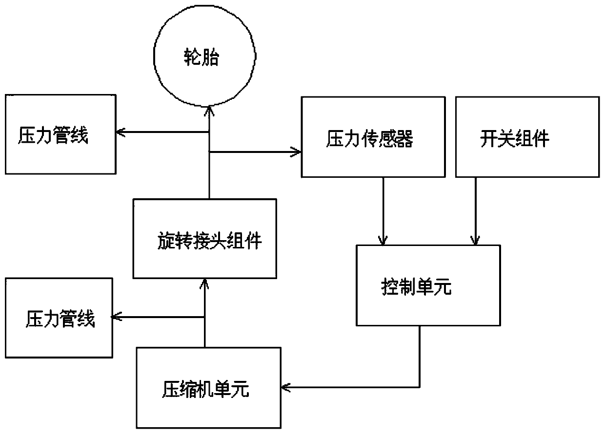
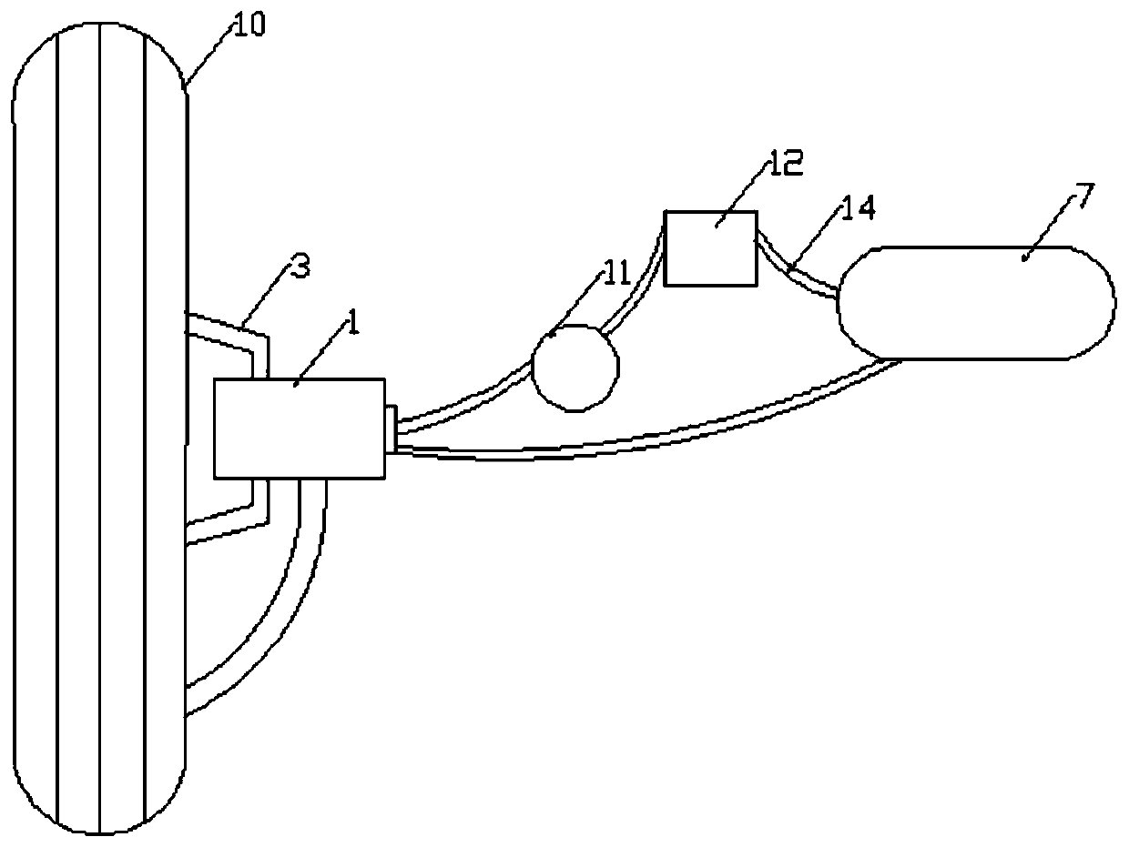
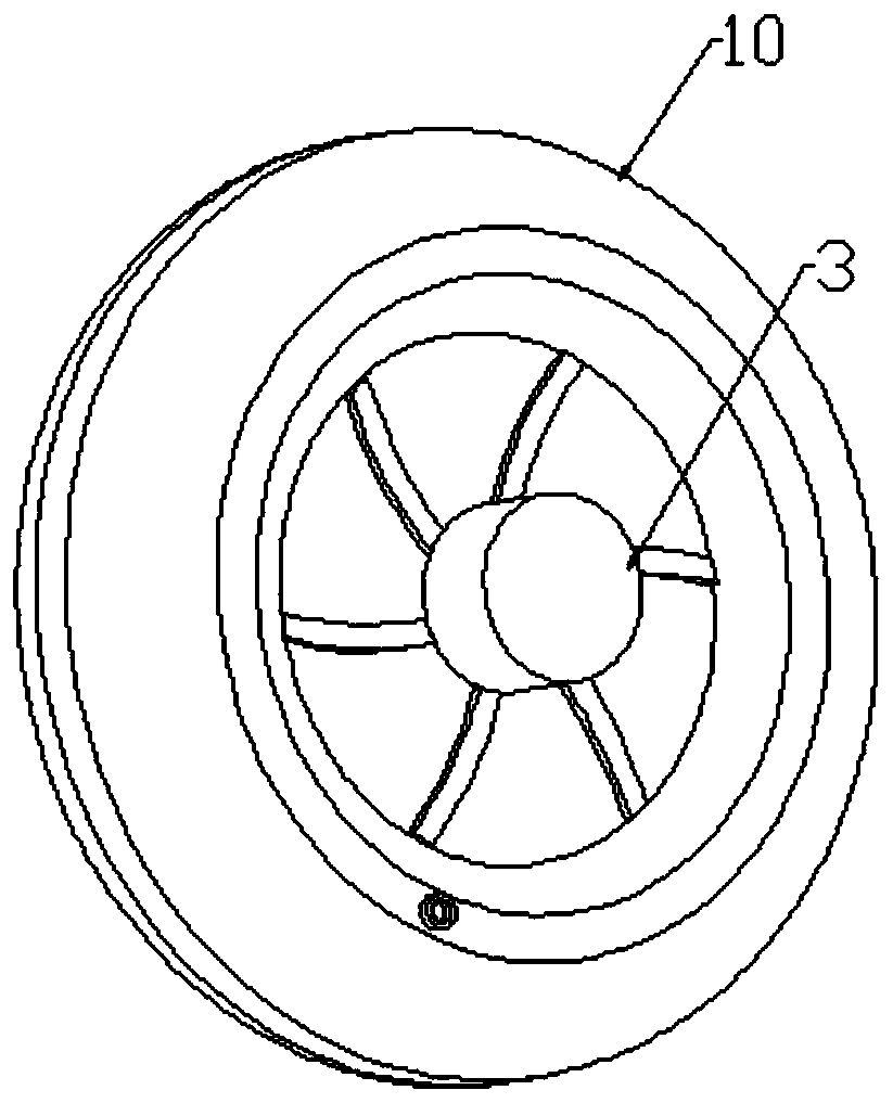
[0027] Such as Figure 1 to Figure 7 As shown, a sensor-based vehicle tire maintenance system and its maintenance method include a pressure sensor 11, a control unit 12, a compressor unit 7, a rotary joint assembly 1, a pressure pipeline E and a switch member. The pressure sensor 11 The port is connected to the input end of the control unit 12, the output end of the control unit 12 is connected to the compressor unit 7 through the hose 14, and the port of the compressor unit 7 is connected to the rotary joint assembly 1 through the pressure pipeline E, and the rotary joint assembly 1 Connected to the air valve of the tire through the pressure line E, the switch member is connected to the control unit 12, the rotary joint assembly 1 includes a housing 2, the inner wall of the housing 2 is fixedly connected with an air chamber 4 and a sleeve 5, the The bottom end of the sleeve 5 abuts against the outside of the air cavity 4, and the sleeve 5 is sleeved with a hollow sleeve rod 6...

Embodiment 2

[0035] Such as Figure 1 to Figure 7 As shown, a sensor-based vehicle tire maintenance system and its maintenance method include a pressure sensor 11, a control unit 12, a compressor unit 7, a rotary joint assembly 1, a pressure pipeline E and a switch member. The pressure sensor 11 The port is connected to the input end of the control unit 12, the output end of the control unit 12 is connected to the compressor unit 7 through the hose 14, and the port of the compressor unit 7 is connected to the rotary joint assembly 1 through the pressure pipeline E, and the rotary joint assembly 1 Connected to the air valve of the tire through the pressure line E, the switch member is connected to the control unit 12, the rotary joint assembly 1 includes a housing 2, the inner wall of the housing 2 is fixedly connected with an air chamber 4 and a sleeve 5, the The bottom end of the sleeve 5 abuts against the outside of the air cavity 4, and the sleeve 5 is sleeved with a hollow sleeve rod 6...


PUM


Abstract

The invention discloses a sensor-based vehicle tire maintenance system and a maintenance method thereof, relating to the technical field of automobile engineering. The sensor-based vehicle tire maintenance system includes a pressure sensor, a control unit, a compressor unit, a rotary joint assembly, a pressure line and a switch member. A port of the pressure sensor is connected with an input end of the control unit; the output end of the control unit is connected with the compressor unit through a hose. According to the system, even when the vehicle moves, a user can monitor the pressure of tires, so that real-time pressure monitoring of the tires is achieved, the system is operated to independently supply pressurized air to each tire of the vehicle, and therefore the user can keep the optimal pressure value in each tire of the vehicle, and practicability is improved.

Description

technical field [0001] The invention relates to the technical field of automobile engineering, in particular to a sensor-based vehicle tire maintenance system and a maintenance method thereof. Background technique [0002] Typically, vehicle tires are inflated with compressed air at a prescribed pressure to provide sufficient cushioning for the tires, the wheels to support the tires and the occupants of the vehicle, and it is important to maintain sufficient tire pressure in the tires of the vehicle. By maintaining optimum tire pressure, the contact patch between the tire and the road is reduced, reducing the frictional contact between the two, however, the pressure inside the tire is not always constant due to various parameters, among which Some of these include but are not limited to pressure loss due to daily commuting, road undulations, overloading, speeding, leaks in the valve area and / or pressure loss in tires due to punctures which can affect the mobility of the vehi...

Claims


Application Information

Patent Timeline
IPC IPC(8): B60C23/04B60C23/00
Inventor 金政张冬平黄胜明王硕吴克平李继萍
Owner 芜湖鑫芯微电子有限公司
Why Eureka
Try Eureka