Train storage battery traction system and method and train

A technology of traction system and storage battery, applied in locomotive propulsion mode, electric vehicle charging technology, locomotive, etc., can solve the problems of wasting power supply energy, wasting hardware resources, and wasting resources, so as to save hardware resources and costs, reduce complexity, The effect of improving usage efficiency

Active Publication Date: 2019-05-10
CRRC QINGDAO SIFANG CO LTD
View PDF7 Cites 6 Cited by
  • Summary
  • Abstract
  • Description
  • Claims
  • Application Information

AI Technical Summary

Problems solved by technology

[0003] However, in the actual use of the subway, the probability of using the battery for traction and power supply is very small. In this way, it is a waste of hardware resources and power supply energy to equi

Method used


Image

  • Train storage battery traction system and method and train
  • Train storage battery traction system and method and train
  • Train storage battery traction system and method and train

Examples


Embodiment 1

[0044] An embodiment of the present application provides a train battery traction system, which will be described in detail below with reference to the accompanying drawings.

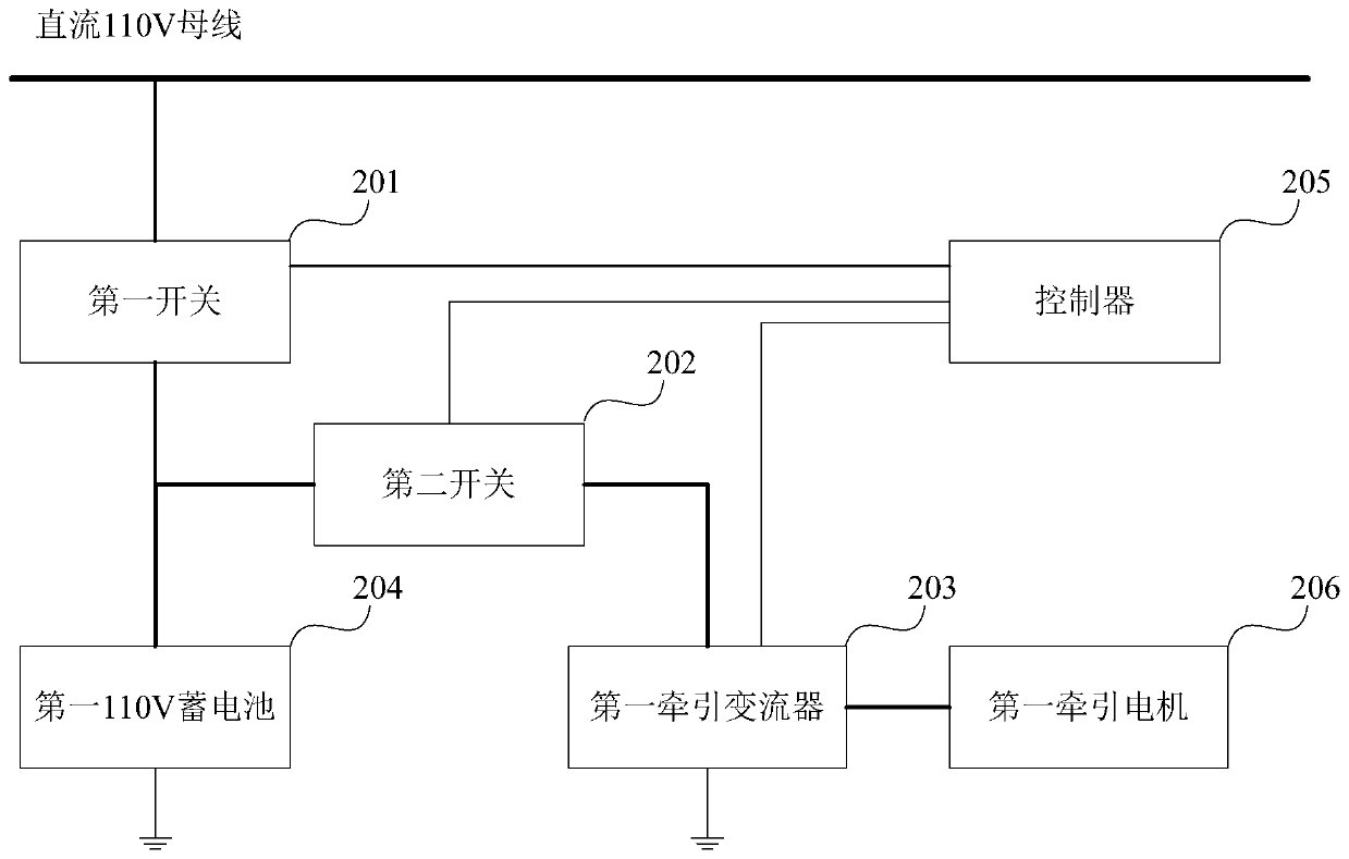
[0045] see figure 2 , which is a train battery traction system provided in Embodiment 1 of the present application.

[0046] The system includes: a first switch 201 , a second switch 202 , a first traction converter 203 , a first 110V battery 204 and a controller 205 . Furthermore, the first traction converter 203 is also connected to the first traction motor 206 .

[0047] It should be noted that "first" and "second" in the embodiments of the present application are only for convenience of explanation and description, and have no limiting function.

[0048] The first switch 201 and the second switch 202 may be circuit breakers, which are used to control the on-off of the circuits where they are located.

[0049] The first 110V battery 204 is connected to a DC 110V bus through the first switch 201 ....

Embodiment 2

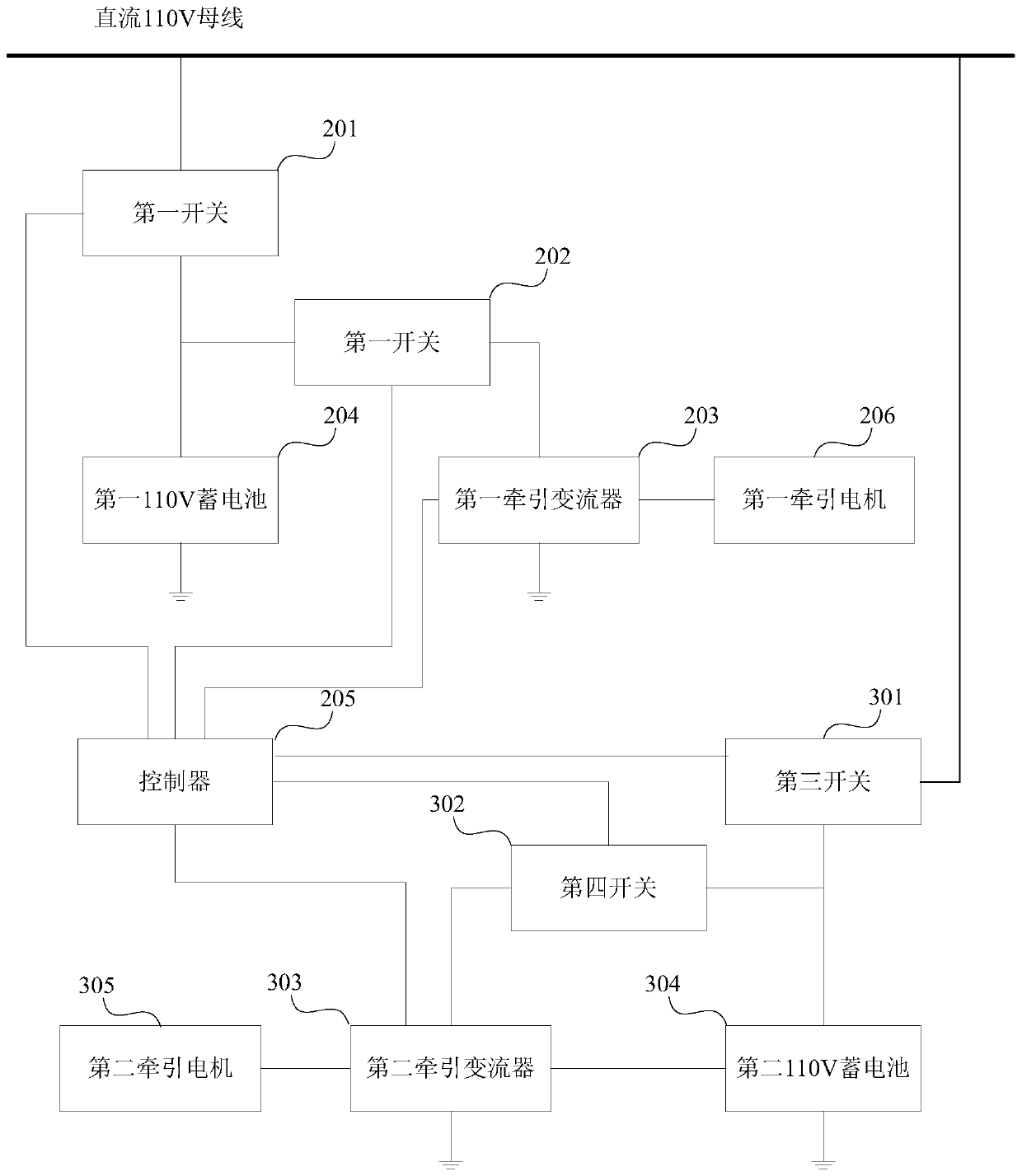
[0061] see image 3 , which is a schematic diagram of another train battery traction system provided in Embodiment 2 of the present application.

[0062] see also Figure 3a , which is a schematic diagram of a specific connection mode of the train battery traction system provided in Embodiment 2 of the present application.

[0063] The system described in the embodiment of the present application is based on the system described in the first embodiment, and further includes a backup part: a third switch 301 , a fourth switch 302 , a second traction converter 303 and a second 110V battery 304 . Furthermore, the second traction converter 303 is also connected to the second traction motor 305 .

[0064] It should be noted that the "third" and "fourth" in the embodiments of the present application are only for convenience of explanation, and have no limiting function.

[0065] The third switch 301 and the fourth switch 302 may be circuit breakers, which are used to control the ...

Embodiment 3

[0080] see Figure 4 , which is a schematic diagram of another train battery traction system provided in Embodiment 3 of the present application.

[0081] The system described in the embodiment of the present application adds a signal acquisition device 401 on the basis of the system described in the third embodiment.

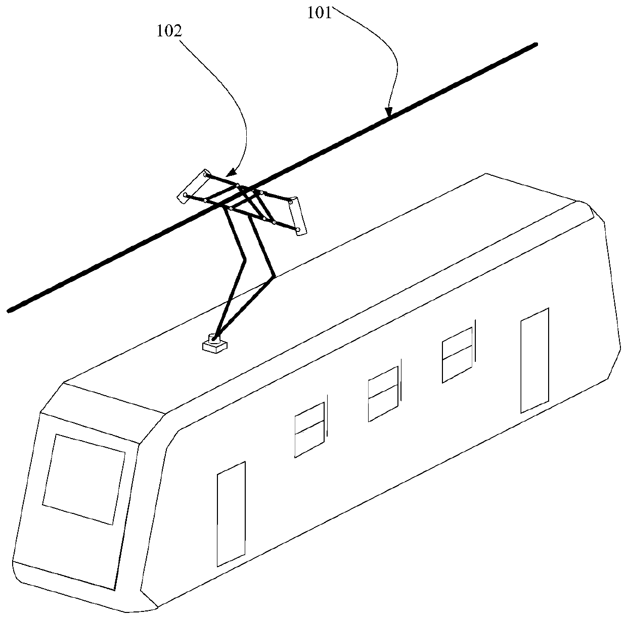
[0082] The signal collection device 401 is configured to determine whether the first pantograph and the second pantograph are raised, and send the results of the first pantograph and the second pantograph raised to the controller 205 .

[0083] The controller 205 may be a control computer of the train.

[0084] Specifically, the signal acquisition device 401 is configured to send the ID of the first pantograph and the effective identifier of the hoisting bow to the controller 205 when the first pantograph is hoisting; When the second pantograph is raising the pantograph, the ID of the second pantograph and the effective identification of the lifting bow are ...


PUM


Abstract

The invention discloses a train storage battery traction system. The system comprises a controller, a first switch, a second switch, a first traction converter and a first 110V storage battery. The first 110V storage battery is connected with a direct current 110V bus through the first switch. The first 110V storage battery is connected with the first traction converter through the second switch.The controller is used for controlling the first switch to be turned on and the second switch to be turned off when confirming that a first pantograph ascends and further used for controlling the first switch to be turned off and the second switch to be turned on when confirming that the first pantograph descends. By the utilization of the system, hardware resources can be saved, the occupied space is reduced, and cost is saved. The invention further provides a train storage battery traction method and a train.

Description

technical field [0001] The invention relates to the technical field of vehicle control, in particular to a train storage battery traction system, a method and a train. Background technique [0002] In the prior art, the subway includes a 110V battery and a 220V battery, and electric energy is obtained from a DC 110V bus and a DC 220V bus respectively. Among them, the 110V battery is used to supply power for the control circuit on the subway, such as lighting system, control system, etc., and the 220V battery is used to provide power for the traction motor. [0003] However, in the actual use of the subway, the probability of using the battery for traction and power supply is very small. In this way, it is a waste of hardware resources and power supply energy to equip each subway with a 220V battery. It takes up more space on the subway. [0004] Therefore, the subway in the prior art is equipped with two batteries of different specifications, which wastes resources and cos...

Claims


Application Information

Patent Timeline
IPC IPC(8): B61C3/02B60L5/18B60L53/20
CPCY02T10/70Y02T10/7072Y02T10/72Y02T30/00Y02T90/14
Inventor 侯小强王东阳邓超月唐兆祥谢立军
Owner CRRC QINGDAO SIFANG CO LTD
Why Eureka
Try Eureka