Beam and column connecting structure

A beam-column connection and connecting pipe technology, which is applied in the direction of building construction and construction, can solve the problems of easy deformation of the stressed part of the column, affecting the appearance of the beam and column connection, troublesome connection, etc., so as to avoid welding Fixed, high strength, high stability effect

Active Publication Date: 2019-05-10
台州航权机械科技有限公司
View PDF6 Cites 5 Cited by
  • Summary
  • Abstract
  • Description
  • Claims
  • Application Information

AI Technical Summary

Problems solved by technology

[0003] In the existing steel structure that uses square tubes as beams and columns, and fixes the ends of the beams on the outside of the columns, generally in order to ensure the stability of the connection of the beams, it is necessary to fix the ends of the beams to the columns through connecting seats, and the connecting seats are generally located at The outside of the beam will not only affect the appearance of the connection between the beam and the column, but the connection seat generally includes a connecting plate made of multiple steel plates, which are fixed by welding, so the connection is more troublesome, and the connection between the end of the beam and the column is more difficult. Small, so that the stressed part of the column is easy to deform, so it is necessary to improve

Method used


Image

  • Beam and column connecting structure
  • Beam and column connecting structure
  • Beam and column connecting structure

Examples


Embodiment Construction

[0029] The following are specific embodiments of the present invention and in conjunction with the accompanying drawings, the technical solutions of the present invention are further described, but the present invention is not limited to these embodiments.

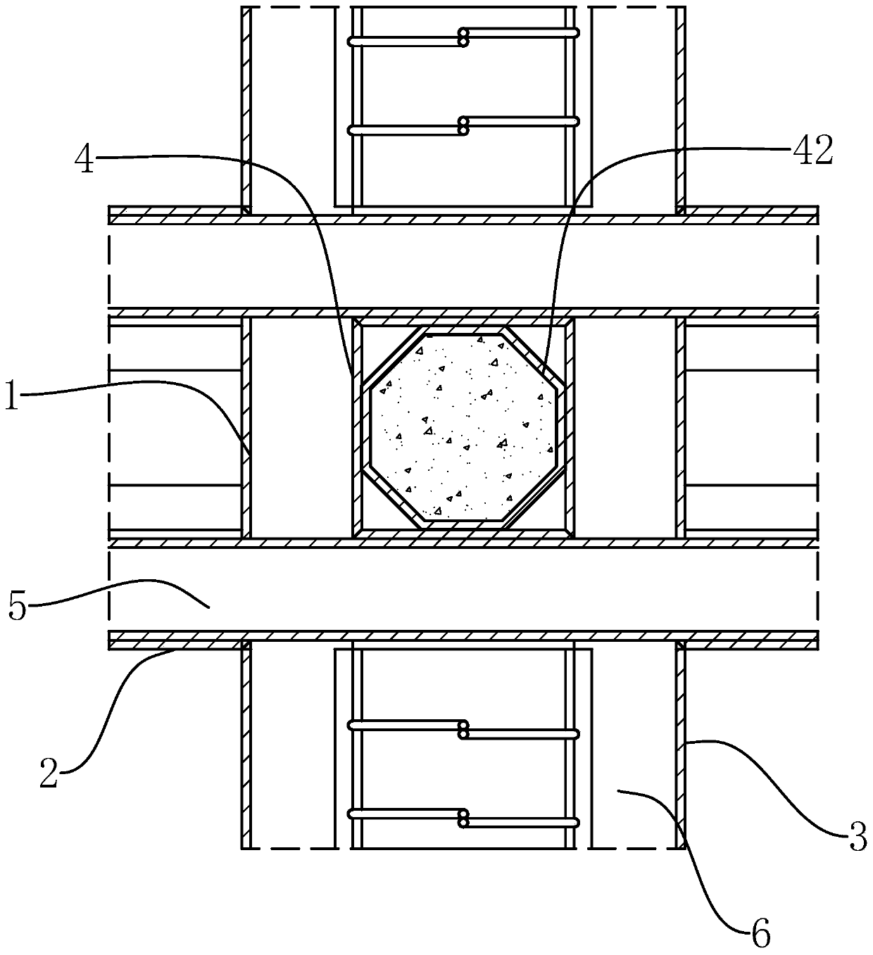
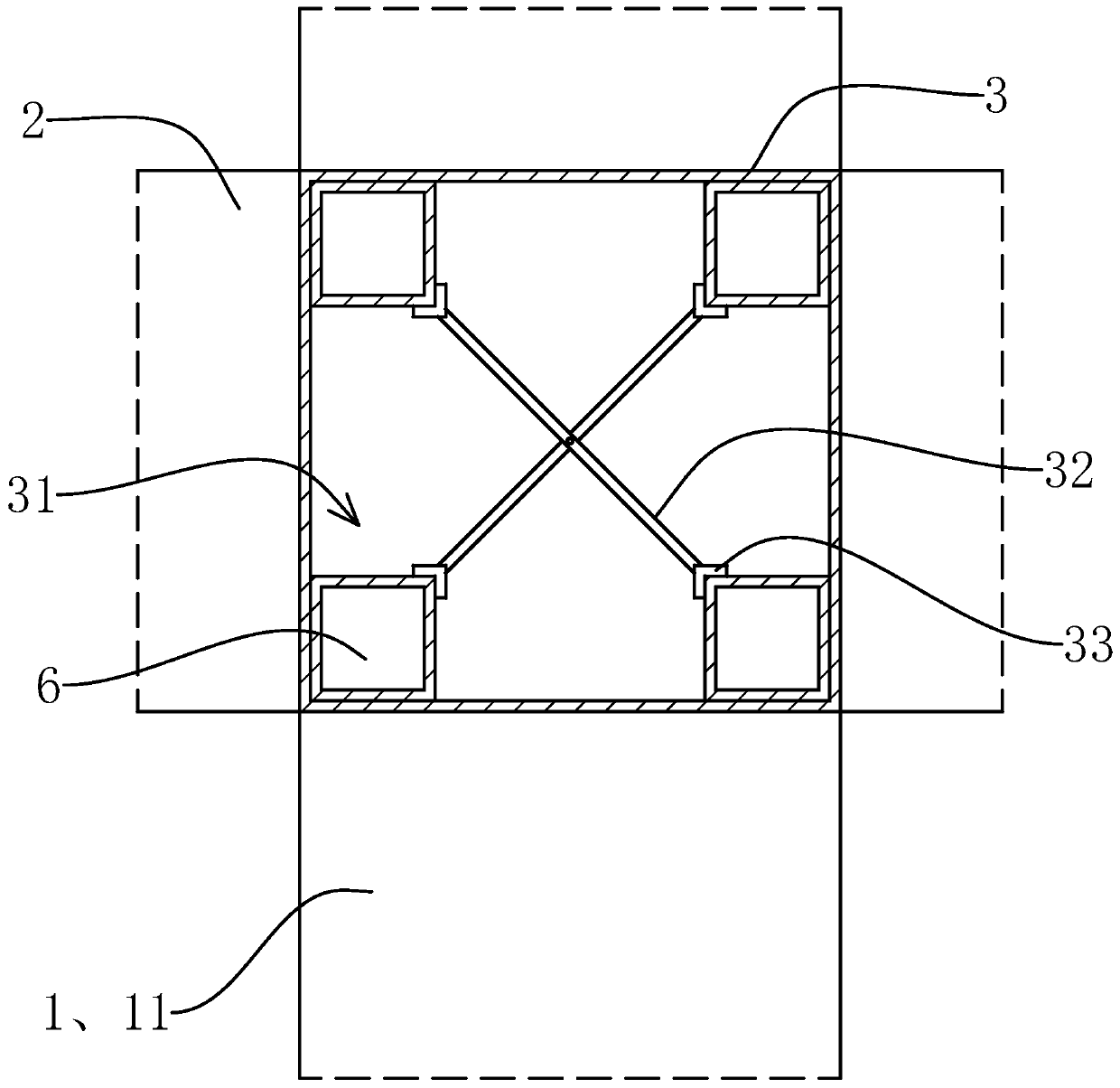
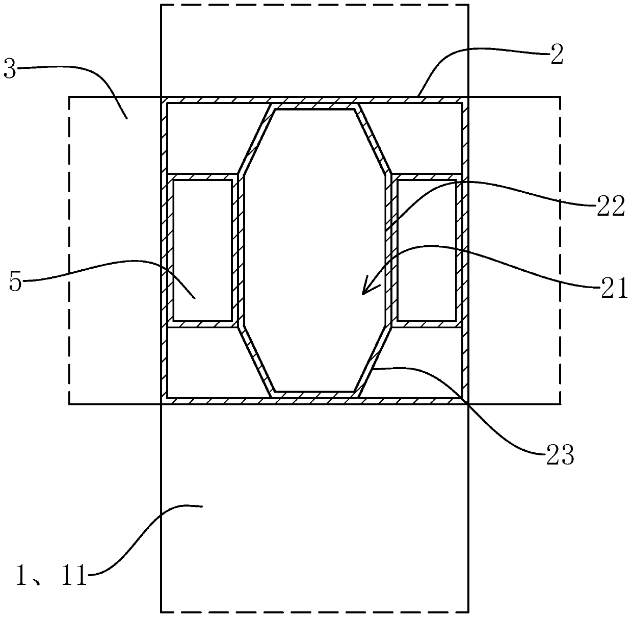
[0030] Such as Figure 1-5 As shown, a beam-column connection structure of the present invention includes a column body and a beam body, the column body includes a column 1, the beam body includes a beam 2 and a longitudinal beam 3, and the column 1, the beam 2 and the longitudinal beam 3 are all hollow rectangular tube structures , and the length direction is perpendicular to each other, the column 1 is vertically arranged, and includes four column plates 11 connected in sequence, two beams 2 and two longitudinal beams 3 are respectively fixed at the same axial position of the column 1, and the two beams 2 Coaxial setting, two longitudinal beams 3 are coaxially arranged, the ends of the two cross beams 2 are respectively ...


PUM


Abstract

The invention provides a beam and column connecting structure, and belongs to the field of steel structures. The problem that an existing beam and column connection strength is low is solved. The beamand column connecting structure comprises a column body and a beam body. The column body comprises a stand column; the beam body comprises cross beams and longitudinal beams; the stand column comprises four column plates; two cross beams and two longitudinal beams are fixed to the stand column. The column body also comprises a central pipe; the central pipe comprises is connected into the columnbody; and the central pipe comprises four central plates. The column body also comprises two transverse pipes and four longitudinal pipes. the two transverse pipes are fixed to the outer side surfacesof the two central plates at the front and rear; the four longitudinal pipes are fixed to the outer side surfaces of the two central plates on the left and right; the two longitudinal pipes are positioned above the two transverse pipes; transverse holes are formed in the two column plates on the left and right, the two ends of the transverse pipe penetrate out of the transverse holes and are located in the two transverse beams, the two transverse pipes are fixed to the inner walls of the left and right sides of the transverse beams, longitudinal holes are formed in the two column plates on the front and back, the longitudinal pipes penetrate out of the longitudinal holes and are located in the longitudinal beams, and the four longitudinal pipes are fixed to four corners of the inner wallsof the longitudinal beams. The connecting structure is higher in strength and better in stability.

Description

technical field [0001] The invention belongs to the technical field of steel structures and relates to a beam-column connection structure. Background technique [0002] Due to its comprehensive advantages such as low carbon, energy saving, green environmental protection, and reusability, steel structures have been widely used in industrial plants, municipal infrastructure construction, cultural, educational and sports construction, electric power, bridges, offshore oil engineering, aerospace and other industries , the market space is gradually expanding. [0003] In the existing steel structure that uses square tubes as beams and columns, and fixes the ends of the beams on the outside of the columns, generally in order to ensure the stability of the connection of the beams, it is necessary to fix the ends of the beams to the columns through connecting seats, and the connecting seats are generally located at The outside of the beam will not only affect the appearance of the ...

Claims


Application Information

Patent Timeline
IPC IPC(8): E04B1/24E04B1/58
Inventor 张丽丽
Owner 台州航权机械科技有限公司
Why Eureka
Try Eureka