
Tapered roller screw rod pair and seal structure

A sealing structure, tapered roller technology, applied in the direction of engine seals, engine components, belts/chains/gears, etc., can solve the problem of not being able to seal with tapered roller screw pairs, achieve reliable contact sealing and reduce leakage amount of effect

Pending Publication Date: 2019-05-10
赵洁
View PDF1 Cites 3 Cited by
  • Summary
  • Abstract
  • Description
  • Claims
  • Application Information

AI Technical Summary

Problems solved by technology

[0006] Different from the structure of the known ball screw pair, the contour line of the screw thread side of the tapered roller screw pair in the axial section of the screw has a greater perpendicularity relative to the center line of the screw, and the tooth groove of the thread is in the It can accommodate the tooth width of a nut thread and two tapered rollers in the axial direction, and has a protruding rib on the outer edge of the screw thread side, so the known ball screw seals and sealing structures cannot be used for tapered rollers. Sealing of roller screw pair

Method used


Image

  • Tapered roller screw rod pair and seal structure
  • Tapered roller screw rod pair and seal structure
  • Tapered roller screw rod pair and seal structure

Examples


no. 1 example

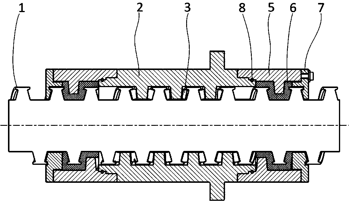
[0070] Below, refer to the attached Figure 1-22 An embodiment of the tapered roller screw pair and its sealing structure of the present invention will be described.

[0071] First of all, regarding the basic structure of the tapered roller screw pair, the basic structure is described in detail in the Chinese patent document CN108561523A. Compared with the present invention, except that the sealing structure used is different, the rest is just a difference in terminology , with exactly the same underlying structure.

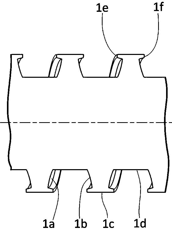
[0072] Such as figure 1 , 2 As shown, conventional screw with figure 1 and 2 The screw 1 shown in the above all adopts the basic external thread structure, the difference is that the profile of the external thread is different, and the profile depth of the conventional screw is relatively small, which is used to partially accommodate the balls, while for figure 1 and figure 2 The lead screw 1 shown in , its profile should have sufficient depth to accommoda...

no. 2 example

[0115] Below, refer to the attached Figure 2-9 And attached Figures 23 to 34 The second embodiment of the tapered roller screw pair and its sealing structure of the present invention will be described.

[0116] Such as Figure 23 , 33 As shown, there are threads on the outer cylindrical surface of the lead screw 1 and the inner cylindrical surface of the nut 2, correspondingly forming external threads and internal threads, and the threads of the lead screw 1 and the nut 2 are arranged in a cross manner in the axial direction, that is The threaded portion on the nut 2 intervenes between adjacent threads of the lead screw 1 to determine the raceway.

[0117] Furthermore, a plurality of tapered rollers 3 are located in the raceway defined by the lead screw 1 and the nut 2, are constrained by the raceway, and flow along the raceway; there are reversers 4 at both ends of the screw thread of the nut 2, and the reverser The reverse guide action surface 4a on 4 is located inside...


PUM


Abstract

The invention discloses a tapered roller screw rod pair and a seal structure. The seal structure is used for seal of the tapered roller screw rod pair, the nut end portions or the nut assembly end portions of the tapered roller screw rod pair are provided with connection heads, seal assemblies which are in one-to-one correspondence with the connection heads and are correspondingly and fixedly connected with the connection heads are provided, the inner surfaces of the seal assemblies are provided with seal screw threads, the seal screw threads are tightly screwed with a screw rod of the taperedroller screw rod pair to form a contact type seal sliding pair, wherein a nut assembly means an assembly formed by pairing use of two nuts. According to the seal structure, the tapered roller screw rod pair and the seal structure are relatively good in reliability.

Description

technical field [0001] The invention relates to a tapered roller screw pair, and also relates to a sealing structure adapted to the tapered roller screw pair. Background technique [0002] The known ball screw pair (GB / T17587.3-1998) is composed of a screw (also known as a lead screw), a nut (also known as a nut), a rolling body, a preloader, a reverser and a dustproof device, among which The rolling elements are balls, which is where the name of the ball screw comes from. The basic principle of the ball screw pair is that an arc-shaped spiral groove is processed on the screw and the nut, and the two cooperate to form a spiral raceway, and the raceway is filled with balls. [0003] When the lead screw is used as the active component, the nut will convert the rotation angle of the lead screw into a linear motion according to the pitch of the corresponding specification, and the passive component can be connected by the nut seat and the nut to realize the linear motion of the...

Claims


Application Information

Patent Timeline
IPC IPC(8): F16H25/22F16J15/16
Inventor 赵洁
Owner 赵洁
Learn More