Dynamic tensile test fixture for test specimen and test method thereof

A technology of dynamic stretching and test fixtures, applied in the direction of applying repetitive force/pulse force to test material strength, using stable tension/pressure to test material strength, measuring device, etc., can solve problems such as damaged test piece test data, Achieve the effect of saving input cost, convenient loading and unloading, and improving applicability

Inactive Publication Date: 2019-05-10
SOUTHEAST UNIV
View PDF9 Cites 4 Cited by
  • Summary
  • Abstract
  • Description
  • Claims
  • Application Information

AI Technical Summary

Problems solved by technology

[0005] Purpose of the invention: Aiming at the problem that the existing test fixture is prone to damage the test data of the test piece during the test, the present invention proposes a dynamic tensile test fixture and test method for the countersunk sheet-shaped test piece

Method used


Image

  • Dynamic tensile test fixture for test specimen and test method thereof
  • Dynamic tensile test fixture for test specimen and test method thereof
  • Dynamic tensile test fixture for test specimen and test method thereof

Examples


Embodiment 1

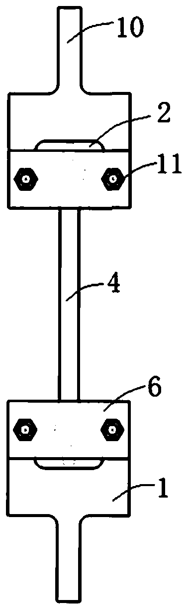
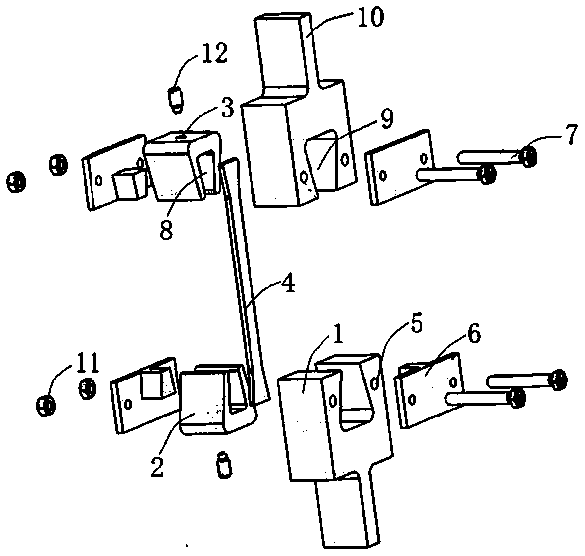
[0046] refer to figure 1 , figure 2 with Figure 6 , the present embodiment provides a dynamic tensile test fixture for a test piece, the dynamic tensile test fixture includes an upper part and a lower part, and the upper part and the lower part are respectively arranged at two ends of the test piece 4 and arranged symmetrically up and down , while the structure and connection of the upper part and the lower part are exactly the same.

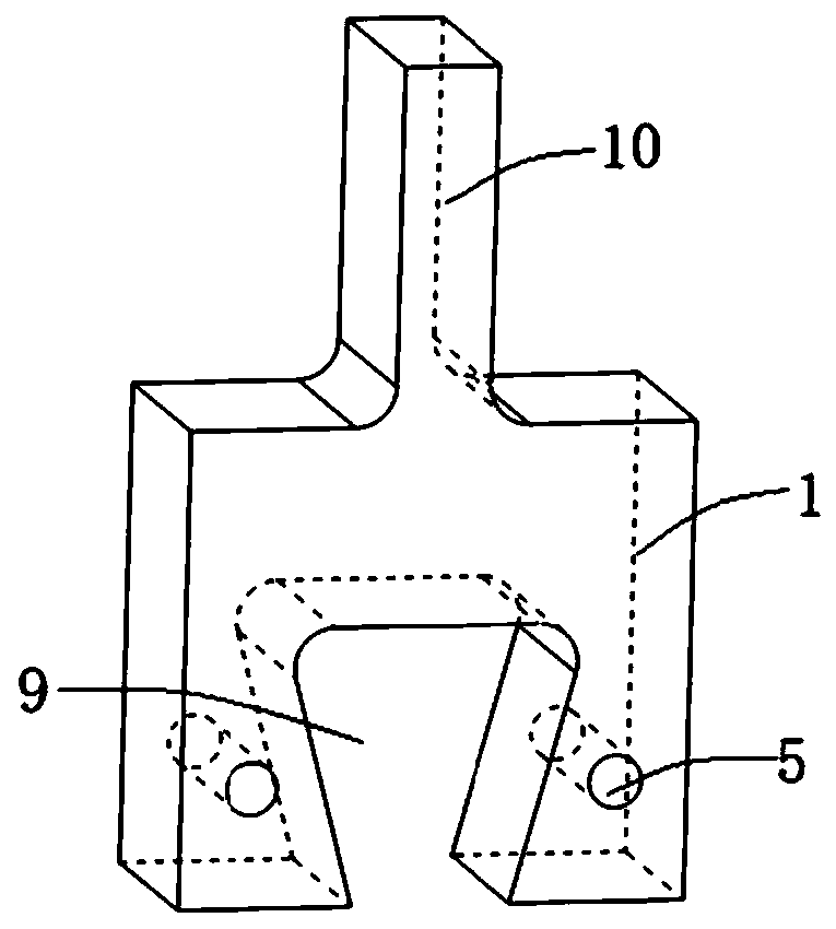
[0047] The upper part includes main clamp 1 and auxiliary clamp 2, refer to image 3 , the middle part of the lower end of the main fixture 1 is provided with a through groove 9, wherein the through groove 9 is used to place the auxiliary fixture 2, specifically, the through groove 9 runs through the main fixture 1, and the through groove 9 is a three-end open part, that is to say, the main fixture The middle part of the lower end of the clamp 1 is hollow, and the size of the hollow part is the same as the outer contour size of the auxiliar...


PUM


Abstract

The invention discloses a dynamic tensile test fixture for a test specimen. The dynamic tensile test fixture for the test specimen comprises an upper part and a lower part; the upper part and the lower part are separately arranged at both ends of the test specimen and are arranged symmetrically up and down, and the upper part and the lower part have the same structure; the upper part comprises a main fixture and an assistant fixture; the central part of the lower end of the main fixture is provided with a through groove; screw holes are arranged on both sides of the through groove; fixed filler sheets are arranged on both sides of the main fixture; the fixed filler sheet is connected to the main fixture through bolts and nuts; the main fixture and the assistant fixture are fixed through the fixed filler sheets; the middle part of the upper end of the assistant fixture is provided with a jackscrew through hole, and the middle part of the lower end is provided with a sample groove; the test specimen is arranged in the sample groove; and the assistant fixture and the test specimen are fixed through a jackscrew adapted to the jackscrew through hole. During the test, the test specimen,the assistant fixture and the main fixture are fixed through the jackscrew and the fixed filler sheets, so as to ensure that the tensile force applied by the testing machine coincides with the axis ofthe test specimen, thereby preventing eccentric loading from adversely affecting the test.

Description

technical field [0001] The invention relates to the technical field of test fixtures, in particular to a dynamic tensile test fixture and a test method for a test piece. Background technique [0002] Tensile and fatigue tests are important methods to obtain the relevant mechanical parameters of various materials. When carrying out this kind of test, the pin or bolt connection structure is often used to connect with the connecting rod of the testing machine, and the method of putting the test piece into the groove of the clamp body is used for testing by tensile and fatigue testing machines. [0003] Chinese Patent Publication No.: CN 106483019 A; Publication Date: March 08, 2017, discloses a tensile fixture for plate-shaped specimens, which is characterized in that the fixture includes: clamp bodies 3, 5, one end of which is provided with a pin Holes 7, and connected with tensile testing machine connecting rods 1, 6 through pins 2, used to ensure that the central axes of th...

Claims


Application Information

Patent Timeline
Patent Type & Authority Applications(China)
IPC IPC(8): G01N3/04G01N3/08G01N3/32
Inventor 费庆国张根西李彦斌张培伟何顶顶
Owner SOUTHEAST UNIV
Why Eureka
Try Eureka