Jaw support structure

A chin and bottom support technology, applied in the field of chin bottom support structure, can solve the problem that the position of the chin bottom support structure cannot be adjusted, and achieve the effect of accurate scanning results

Inactive Publication Date: 2019-05-14
GUIZHOU UNIV
View PDF7 Cites 0 Cited by
  • Summary
  • Abstract
  • Description
  • Claims
  • Application Information

AI Technical Summary

Problems solved by technology

[0003] The purpose of the present invention is to provide a chin bottom support structure to solve the problem that the position of the chin bottom support structure cannot be adjusted in the above-mentioned background technology

Method used


Image

  • Jaw support structure
  • Jaw support structure

Examples


Embodiment Construction

[0014] The following will clearly and completely describe the technical solutions in the embodiments of the present invention with reference to the accompanying drawings in the embodiments of the present invention. Obviously, the described embodiments are only some, not all, embodiments of the present invention. Based on the embodiments of the present invention, all other embodiments obtained by persons of ordinary skill in the art without making creative efforts belong to the protection scope of the present invention.

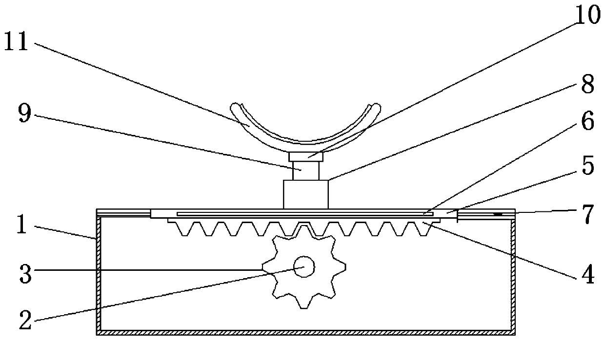
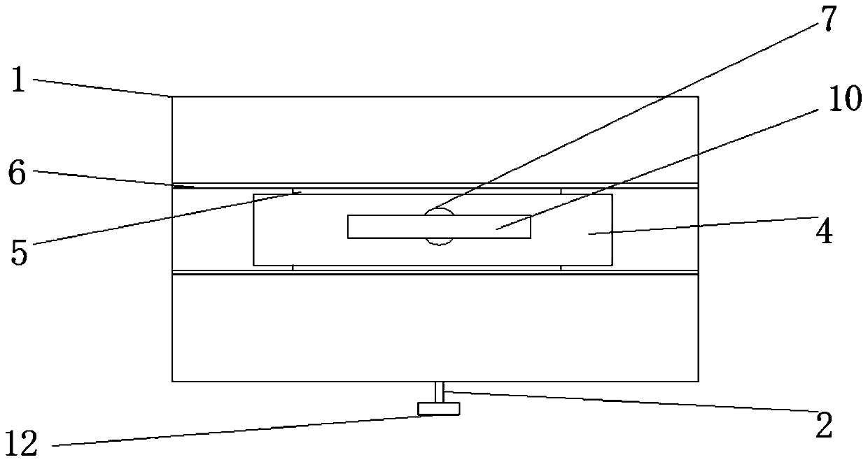
[0015] see Figure 1-2 , the present invention provides a technical solution: a chin bottom support structure, including a base box 1, a rectangular hole is opened on the top of the base box 1, a rotating shaft 2 is provided through the front and rear ends of the base box 1, and the rotating shaft The rear end of 2 is fixed on the inner cavity rear wall of the base box 1 through bearings, the front end of the rotating shaft 2 penetrates the front end wall of t...


PUM


Abstract

The invention discloses a jaw support structure. The jaw support structure comprises a base box body, wherein a rotating shaft penetrates through the front and rear ends of the base box body, the rearend of the rotating shaft is fixed on the rear wall of an inner cavity of the base box body through a bearing, the front end of the rotating shaft penetrates through the front end wall of the base box body and extends out of the base box body, the front end of the rotating shaft is provided with a rotating handle, the middle of the rotating shaft is sleeved with a gear, the upper end of the gearis meshed with a rack, the top of the rack is provided with a moving plate, the front and rear end faces of the moving plate are provided with sliding strips, corresponding positions of the sliding strips are provided with sliding grooves, the top end of the moving plate is provided with a fixed threaded tube, the top of the fixed threaded tube is provided with a movable threaded rod, the top of the movable threaded rod is provided with a bearing, and the top of the bearing is provided with a jaw support plate. The jaw support structure has the advantages that the structure is simple, and theupper, lower, left and right positions of the support can be conveniently adjusted.

Description

technical field [0001] The invention relates to the technical field of medical devices, in particular to a chin bottom support structure. Background technique [0002] The hospital uses an optical coherence tomography scanner to scan the retina of ophthalmology patients. The scanner is equipped with a chin rest structure, but these chin rest structures are fixed, and the patient cannot ensure that the eyes are aligned with the eyepiece during the examination. Contents of the invention [0003] The purpose of the present invention is to provide a chin support structure to solve the problem that the position of the chin support structure cannot be adjusted in the background art. [0004] In order to achieve the above object, the present invention provides the following technical solution: a chin bottom support structure, including a base box, the front and rear ends of the base box are provided with a rotating shaft, and the rear end of the rotating shaft is fixed on the bot...

Claims


Application Information

Patent Timeline
Patent Type & Authority Applications(China)
IPC IPC(8): A61B3/00A61B3/10
Inventor 李媛媛袁建刘仁君管传宝李炜烙杨勤
Owner GUIZHOU UNIV
Why Eureka
Try Eureka