Electrical connector

A technology of electrical connectors and sockets, which is applied in the direction of connection, two-part connection devices, circuits, etc., can solve the problems of reduced service life, poor structural strength, structural strength fracture, etc., and achieve improved structural strength, large bonding force, The effect of multiple contact areas

Inactive Publication Date: 2019-05-14
PLASTRON PRECISION
View PDF4 Cites 0 Cited by
  • Summary
  • Abstract
  • Description
  • Claims
  • Application Information

AI Technical Summary

Problems solved by technology

However, if the plastic injection molding only covers the frame 12 and the terminal module 13 in a surface contact manner, the structural strength will be poor due to the small contact area and insufficient bonding force. For device 1, its service life will undoubtedly be greatly reduced. Therefore, the Taiwan Patent No. M5333

Method used


Image

  • Electrical connector
  • Electrical connector
  • Electrical connector

Examples


Embodiment Construction

[0024] The present invention will be described in detail below in conjunction with the accompanying drawings and embodiments.

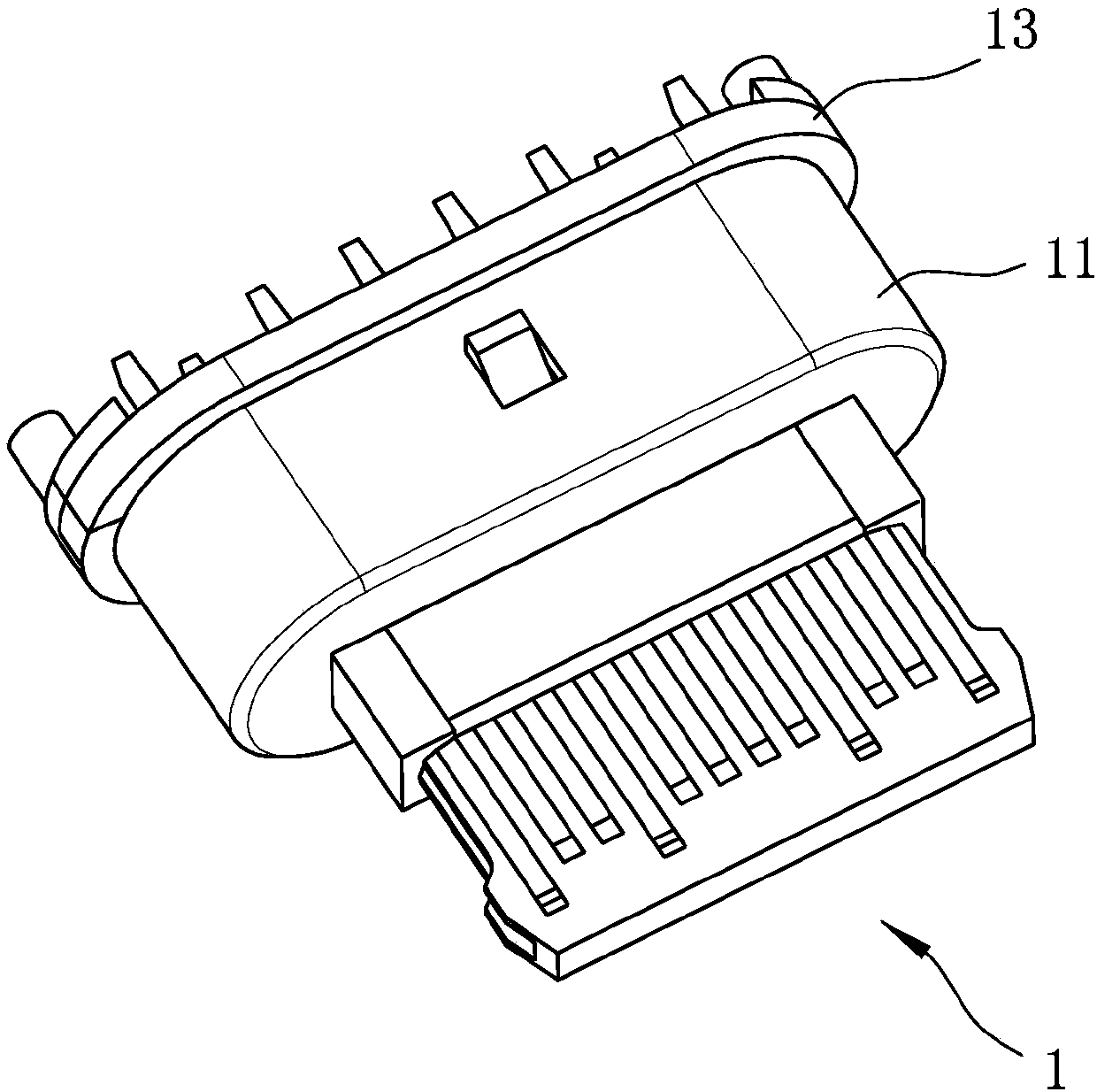
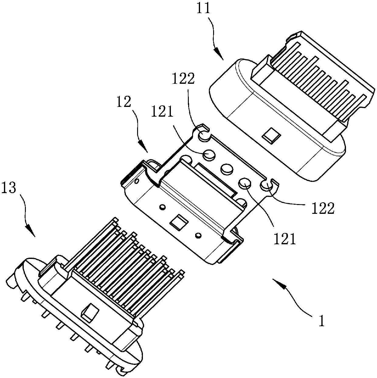
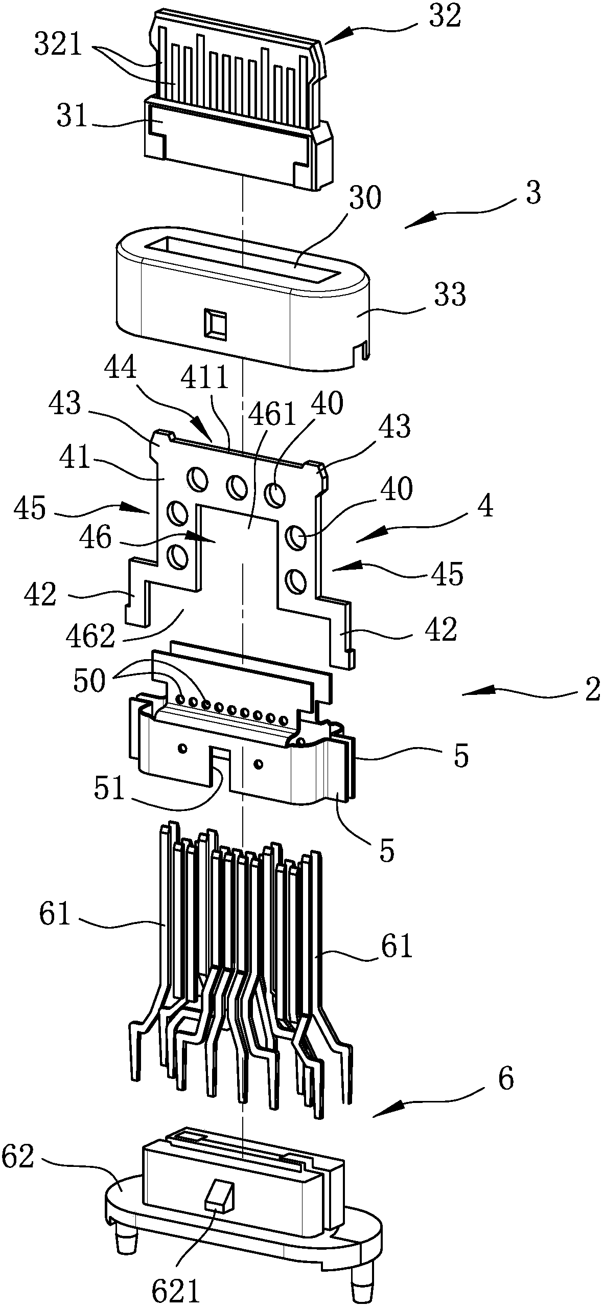
[0025] refer to image 3 , Figure 4 and Figure 5 The first embodiment of the electrical connector 2 of the present invention includes a socket 3 made by plastic injection molding and surrounding a setting space 30 , inserted into the setting space 30 of the socket 3 and opening a plurality of channels The frame 4 of the hole 40, two clamping parts 5 that cooperate with each other to clamp the frame 4 up and down and open a plurality of openings 50 continuously along the left and right directions, and the frame 4 is sandwiched and arranged on the receiving seat 3 terminal module 6 on the The socket 3 includes a base 31 , a plate body 32 protruding forward from the front end of the base 31 , and an insulation sleeve that is sleeved on the base 31 and defines the installation space 30 together with the base 31 . Section 33. The board portion 32 ha...


PUM

PropertyMeasurementUnit
Thicknessaaaaaaaaaa

Abstract

An electrical connector comprises a bearing seat with an arrangement space; a framework, which is inserted into the arrangement space; and a terminal module. The framework defines a notch that protrudes forwards. The notch is arranged in the arrangement space. The terminal module comprise two terminal sets, which penetrate the bearing seat and are arranged on the upper side and lower side of the framework respectively. When the bearing seat is arranged on the framework through injection moulding, through the notch, a large contact area and a large binding force can be obtained, and thus the structural strength is enhanced after moulding.

Description

technical field [0001] The invention relates to a connection assembly, in particular to an electrical connector. Background technique [0002] Universal Serial Bus (USB) is one of the most popular connector types at present. Its specifications are formulated by the USB Association (USB-IF). The Type C USB connector, which focuses on miniaturization and higher transmission speed, It is widely used because it conforms to the trend of the public pursuing thinness. Another feature of the Type C USB connector is that the width of the upper and lower ends of the connecting part is exactly the same, which allows users to plug in directly without having to bother to rotate the connector when connecting electronic products. When the shape of the slot cannot be directly seen , the user does not need to spend a lot of time on trial and error in order to correspond to the shape, which can improve the convenience and installation speed. [0003] Although the appearance and specificatio...

Claims


Application Information

Patent Timeline
IPC IPC(8): H01R13/502H01R13/504
CPCH01R13/405H01R13/506H01R2107/00H01R24/60H01R13/502H01R13/04H01R13/516H01R13/627H01R13/40
Inventor 郭昭正
Owner PLASTRON PRECISION
Why Eureka
Try Eureka