Jacking pipe joint inner wall concrete stress monitoring method based on optical fiber sensing

An optical fiber sensing and stress monitoring technology, which is applied in the direction of force measurement, measurement force, and measurement device by measuring the change of optical properties of materials when they are stressed. problems such as location, affecting the construction progress of the pipe jacking project, etc., to achieve the effects of light weight, long monitoring distance and accurate positioning

Inactive Publication Date: 2021-02-19
ANHUI UNIV OF SCI & TECH +2
View PDF5 Cites 2 Cited by
  • Summary
  • Abstract
  • Description
  • Claims
  • Application Information

AI Technical Summary

Problems solved by technology

However, the existing technology lacks concrete stress detection on the inner wall of the pipe joint. When the inside of the pipe joint is blocked, the blocked position cannot be accurately judged, so it cannot be dealt with in time, which seriously affects the construction progress of the pipe jacking project.

Method used


Image

  • Jacking pipe joint inner wall concrete stress monitoring method based on optical fiber sensing
  • Jacking pipe joint inner wall concrete stress monitoring method based on optical fiber sensing
  • Jacking pipe joint inner wall concrete stress monitoring method based on optical fiber sensing

Examples


Embodiment 1

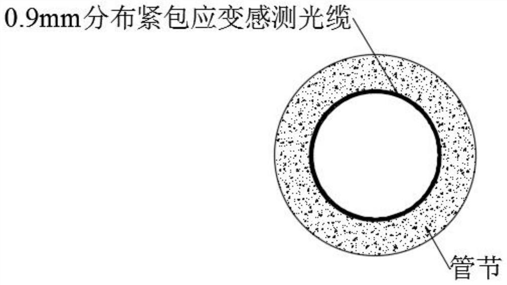
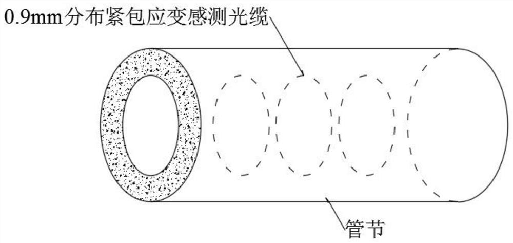
[0036] like Figure 1-2 As shown, a method for monitoring concrete stress on the inner wall of pipe jacking pipe joints based on optical fiber sensing includes the following steps:

[0037] S1. Clean the surface of the structure where the optical cable is laid on the three sections of the pipe section, remove impurities and make an indicator line on the surface of the structure, and paint a layer of epoxy resin glue on the indicator line according to a certain width;

[0038] S2. Lay out 0.9mm glass fiber composite base optical cable along one direction on the glue, and press the dense optical cable with rollers to make the optical cable fully contact with the glue;

[0039] S3. After the optical cable is laid, apply a layer of epoxy glue on the upper part of the optical cable again, press it tightly with a roller again, and then use cloth tape to temporarily fix the optical cable to prevent the optical cable from falling off. After the epoxy glue is cured for about 24 hours, ...

Embodiment 2

[0054] like Figure 1-2 As shown, a method for monitoring concrete stress on the inner wall of pipe jacking pipe joints based on optical fiber sensing includes the following steps:

[0055]S1. Clean the surface of the structure where the optical cable is laid on the three sections of the pipe section, remove impurities and make an indicator line on the surface of the structure, and paint a layer of epoxy resin glue on the indicator line according to a certain width;

[0056] S2. Lay out 0.9mm glass fiber composite base optical cable along one direction on the glue, and press the dense optical cable with rollers to make the optical cable fully contact with the glue;

[0057] S3. After the optical cable is laid, apply a layer of epoxy glue on the upper part of the optical cable again, press it tightly with a roller again, and then use cloth tape to temporarily fix the optical cable to prevent the optical cable from falling off. After the epoxy glue is cured for about 24 hours, i...


PUM


Abstract

The invention discloses a jacking pipe joint inner wall concrete stress monitoring method based on optical fiber sensing, and the method comprises the following steps: S1, cleaning a pipe joint ring,making an optical cable laying indication line, and brushing epoxy resin glue; S2, laying an optical cable, and pressing the compact optical cable by using a roller; S3, coating the upper part of theoptical cable with a layer of epoxy resin glue again, temporarily fixing the optical cable with a cloth-based adhesive tape, and curing the epoxy resin glue; S4, enabling the optical cable to be connected with data acquisition equipment, calculating the dependent variable of the optical fiber by measuring the frequency drift amount and the reflection wavelength drift amount of the back natural Brillouin scattering light in the optical fiber, and measuring the stress change of the concrete on the inner wall of the pipe joint. The annular glass fiber composite base optical cables are arranged onthe three sections of the pipe joint, the frequency drift amount and the reflection wavelength drift amount of back natural Brillouin scattering light in the optical fiber are measured through the data acquisition equipment, and then the dependent variable of the optical fiber is calculated and used for representing concrete stress changes.

Description

technical field [0001] The invention relates to the field of pipe jacking stress monitoring, in particular to a method for monitoring concrete stress on the inner wall of pipe jacking joints based on optical fiber sensing. Background technique [0002] As a trenchless technology, pipe jacking technology has the advantages of fast construction speed, high degree of automation, saving human resources, and harmonious coexistence with the environment. It has been increasingly used in the construction of underground tunnels. In order to achieve long-distance pipe jacking, the friction between the pipe and the surrounding soil or surrounding rock should be reduced and overcome as much as possible. Common measures include reducing the jacking distance between the relays, increasing the jacking force, and injecting lubricating materials, etc. However, under complex geological conditions, long-distance pipe jacking still often encounters the situation that the jacking is blocked, an...

Claims


Application Information

Patent Timeline
Patent Type & Authority Applications(China)
IPC IPC(8): G01L1/24
CPCG01L1/246G01L1/247
Inventor 刘吉敏程桦曹广勇陈平
Owner ANHUI UNIV OF SCI & TECH
Why Eureka
Try Eureka