Novel rapid-insertion self-locking connection mechanism

A connection mechanism and self-locking technology, which is applied to the connection, parts of the connection device, coupling device, etc., can solve the problems of cost increase, insufficient holding force, high structural cost, etc., and achieve high mechanism reliability, high degree of freedom of use, The effect of simple manufacturing process

Inactive Publication Date: 2019-05-14
SHANGHAI AEROSPACE SCI & IND ELECTRIC APPLIANCE RES INST
View PDF4 Cites 7 Cited by
  • Summary
  • Abstract
  • Description
  • Claims
  • Application Information

AI Technical Summary

Problems solved by technology

[0002] With the development of technology and different demands, the quick lock mechanism with high installation density and fast installation has gradually replaced the conventional mechanism and become the mainstream. There are a large number of different forms of quick lock mechanism on the market, mainly claw type, that is, relying on elastic parts Opening or shrinking makes the claw mechanism cooperate with the slot to achieve locking. However, the current claw mechanism mainly has disadvantages such as insufficient holding force, high structural cost, and cost increase caused by high material elasticity requirements, making the product of the quick lock mechanism The price is high, the reliability is insufficient, and it is difficult to achieve popularization

Method used


Image

  • Novel rapid-insertion self-locking connection mechanism
  • Novel rapid-insertion self-locking connection mechanism
  • Novel rapid-insertion self-locking connection mechanism

Examples


Embodiment Construction

[0027] The present invention will be further described in detail below in conjunction with the accompanying drawings and embodiments.

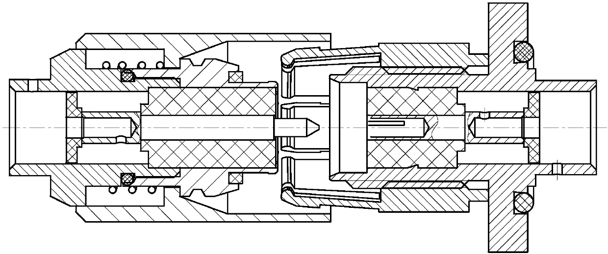
[0028] In this embodiment, the SMA type radio frequency coaxial connector is used as a model to describe in detail.

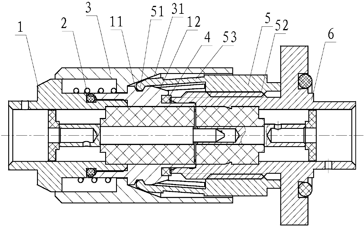
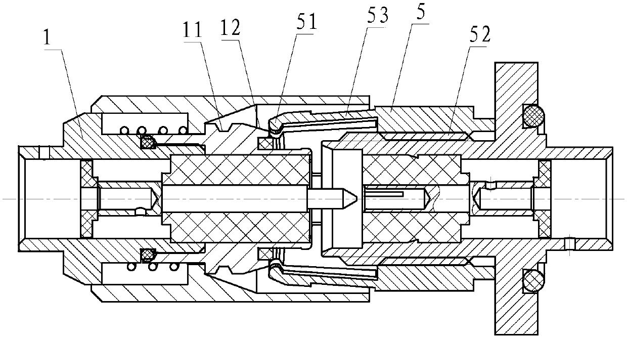
[0029] A new type of quick-plug self-locking connection mechanism shown in this embodiment is roughly composed of 6 parts, mainly divided into, plug body 1, spring 2, unlocking sleeve 3, elastic seal 4, elastic claw 5, socket body 6.

[0030] Same as the conventional quick lock mechanism, the unlocking mechanism is arranged at the plug end, and the unlocking sleeve 3 is assembled and interconnected with the plug main body 1 to form a whole. A trapezoidal groove 11 is provided at an appropriate position at the front end of the plug body 1 as a locking point of the quick lock mechanism. The unlocking sleeve 3 ensures that it can slide relative to the plug body and lock the stroke through the elasticity of the spring 2. The slid...


PUM


Abstract

The invention discloses a novel rapid-insertion self-locking connection mechanism. The novel rapid-insertion self-locking connection mechanism comprises a plug main body (1), a spring (2), an unlocking sleeve (3), an elastic claw (5) and a socket main body (6), wherein the elastic claw (5) is arranged at an interface of the socket main body (6), a hook claw (51) is arranged at the bottom of the elastic claw (5), a trapezoid groove (11) is formed in an outer side of the plug main body (1), the spring (2) is arranged between the plug main body (1) and the unlocking sleeve (3) and is used for providing an axial elastic force for the plug main body (1) and the unlocking sleeve (3), a sliding rail (31) is formed in the unlocking sleeve (3) and is sued for the elastic claw to slide, an inclinedsurface is arranged at the bottom of the sliding rail (31), and the bottom of the sliding rail (31) is in closely contact with the hook claw (51) during the locking process so that the hook claw (51)is locked in the trapezoid groove (11). Rapid insertion and self locking are achieved by matching of the trapezoid groove and the unlocking sleeve in a sliding rail surface way.

Description

technical field [0001] The invention relates to a quick-insert self-locking connector interconnection mechanism, which is suitable for different types of connectors. It can be mainly applied to the mechanism interconnection quick lock of a circular connector, and can also be modified to provide square and other special-shaped connector interfaces. Interface quick lock solution. Background technique [0002] With the development of technology and different needs, the quick-lock mechanism with high installation density and fast installation has gradually replaced the conventional mechanism and become the mainstream. Opening or shrinking makes the claw mechanism cooperate with the slot to achieve locking. However, the current claw mechanism mainly has disadvantages such as insufficient holding force, high structural cost, and cost increase caused by high material elasticity requirements, making the product of the quick lock mechanism The price is high, the reliability is insuf...

Claims


Application Information

Patent Timeline
Patent Type & Authority Applications(China)
IPC IPC(8): H01R13/639H01R13/629
Inventor 李苏云杜如民林海毅
Owner SHANGHAI AEROSPACE SCI & IND ELECTRIC APPLIANCE RES INST
Why Eureka
Try Eureka