A kind of mems driver based on zipper comb and its working method

A driver and zipper technology, applied in the field of micro-electromechanical, can solve the problems of large structure and difficult laser design, small rotation radius tuning range, small tuning range rotation radius, etc., and achieve the effect of compact structure, long rotation radius and large tuning range

Active Publication Date: 2020-09-29
SHANDONG UNIV
View PDF8 Cites 0 Cited by
  • Summary
  • Abstract
  • Description
  • Claims
  • Application Information

AI Technical Summary

Problems solved by technology

[0004] Some of the vertical MEMS drivers that move in the plane that are applied to external cavity tunable lasers now have a large rotation radius but a relatively small tuning range, such as the MEMS rotating mirror design applied to external cavity tunable lasers by Ionon in 2003; There are also some that have a large tuning range but a small rotation radius, and the large structure is not easy to design lasers, such as the MEMS rotating mirror design of Tsinghua University in Taiwan.
Existing designs cannot meet the requirements of compact structure, large tuning range, long rotation radius, and narrow linewidth required by external cavity tunable lasers at the same time

Method used


Image

  • A kind of mems driver based on zipper comb and its working method
  • A kind of mems driver based on zipper comb and its working method
  • A kind of mems driver based on zipper comb and its working method

Examples


Embodiment 1

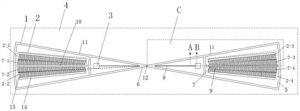
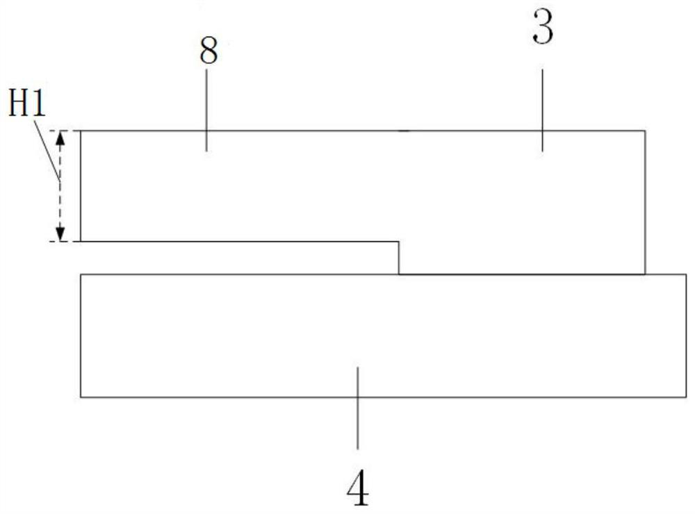
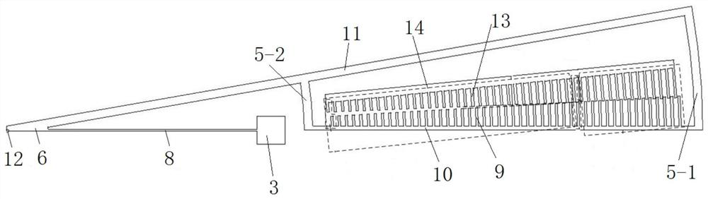
[0045] A zipper comb based MEMS actuator such as Figure 1~4 As shown, it includes a movable part 1, a fixed comb 2, a fixed anchor point 3 and a base layer 4, and the fixed comb 2 and the fixed anchor point 3 are fixed on the base layer 4;

[0046] The movable part 1 includes a radial truss, an arc truss 5, a connecting part 6, a movable comb 7 and an elastic beam 8, and the arc truss 5 is set at the arc position with the imaginary axis point 12 as the center. At the arc position corresponding to the radius, the radial truss is arranged along the radial direction, and the radial truss includes a first radial truss 10 connected with the movable comb 9 and a second radial truss connected with the converging end of the connecting part 6 to the truss 11, the first radial truss 10 and the second radial truss 11 and the arc truss 5 (here the arc truss 5 includes the first radial truss 10 and the second radial truss The arc truss 5-1 at the end of 11 and the arc truss 5-2 located i...

Embodiment 2

[0051] A kind of MEMS driver based on the zipper comb, the structure is as shown in embodiment 1, and its difference is that, in every pair of fixed comb 2 and movable comb 7, the logarithm of fixed comb and movable comb is 49 pairs, does not apply When the voltage is applied, the initial overlapping comb teeth of the fixed comb 2 and the movable comb 7 are the 15th pair of comb teeth counted from the outside. In the present invention, the logarithm of the fixed comb and the movable comb generates enough driving force, and leaves enough length for the elastic beam to make the driver rotate around the imaginary axis, and the unilateral rotation is preferably more than 2.5°.

Embodiment 3

[0053] A kind of MEMS driver based on zipper comb, the structure is as shown in embodiment 2, and its difference is that the center angle corresponding to the outermost movable comb and fixed comb is 3 °, and the width is 8m, in order to ensure the structure It is compact and can be designed with a rotation angle of no more than 3° on one side.


PUM


Abstract

The invention relates to an MEMS driver based on zipper comb teeth and a working method of the MEMS driver, and belongs to the technical field of micro electro mechanical systems, the MEMS driver comprises a movable part, a fixed comb, a fixed anchor point and a base layer, and the fixed comb and the fixed anchor point are both fixed on the base layer; the fixed comb and the movable comb are distributed in pairs in a crossed mode, and when voltage is applied, the movable part rotates around an imaginary axis point on the outer side of the driver in the same plane. Compared with the prior art,the driver adopts a zipper comb tooth structure; on the same comb, the comb teeth with different radiuses correspond to different central angles; different from ordinary zipper comb teeth, the smallerthe radius is, the smaller the central angle is; the comb teeth with large radius are firstly driven to drive the comb teeth with small radius, drives the small-radius comb teeth to drive, the small-radius comb tooth displacement limitation caused by the thickness of the truss can be reduced; rotation space between comb teeth is fully utilized, the structure is simplified, the driver can also beapplied to an outer cavity tunable laser, a grating or a plane mirror can be installed, and narrow linewidth and mode-hopping-free tuning of the laser is achieved.

Description

technical field [0001] The invention relates to a MEMS device structure, in particular to a zipper comb-based MEMS driver and a working method thereof, belonging to the field of micro-electromechanical technology. Background technique [0002] Tunable light sources in the near-infrared band have always attracted the attention of many fields, and have shown very broad application prospects in many industrial and scientific research purposes. The unique advantages of tunable lasers are that its structure is relatively short and compact, the spectral tuning range is high, the output laser line width is relatively narrow, the production can be scaled and systematic, and the price is reasonable. , multi-industry process inspection, atmospheric environment analysis and pollution detection, medical equipment, radar and other aspects have a wide range of application space. The common tunable lasers on the market can be roughly divided into distributed Bragg reflective lasers, distr...

Claims


Application Information

Patent Timeline
Patent Type & Authority Patents(China)
IPC IPC(8): B81B3/00B81B7/02B81C1/00
Inventor 刘兆军李文睿秦增光关晨丛振华张行愚
Owner SHANDONG UNIV
Why Eureka
Try Eureka