Mechanism capable of realizing automatic door opening and closing and applying pressing force

A pressing force, automatic technology, applied in the direction of power control mechanism, wing fan control mechanism, door/window accessories, etc., can solve the problems of space-consuming, large rotating space, time-consuming and labor-intensive, and achieve system simplification and high reliability. , the effect of great practical value

Pending Publication Date: 2019-05-17
ZHENGZHOU RES INST OF MECHANICAL ENG CO LTD
View PDF0 Cites 2 Cited by
  • Summary
  • Abstract
  • Description
  • Claims
  • Application Information

AI Technical Summary

Problems solved by technology

The current conventional design is that the switch of the airtight door is a hinge structure. The opening and closing of the airtight door requires a relatively large rotating space. In additio

Method used


Image

  • Mechanism capable of realizing automatic door opening and closing and applying pressing force
  • Mechanism capable of realizing automatic door opening and closing and applying pressing force
  • Mechanism capable of realizing automatic door opening and closing and applying pressing force

Examples


Embodiment Construction

[0021] The present invention will be further described below in conjunction with example (accompanying drawing).

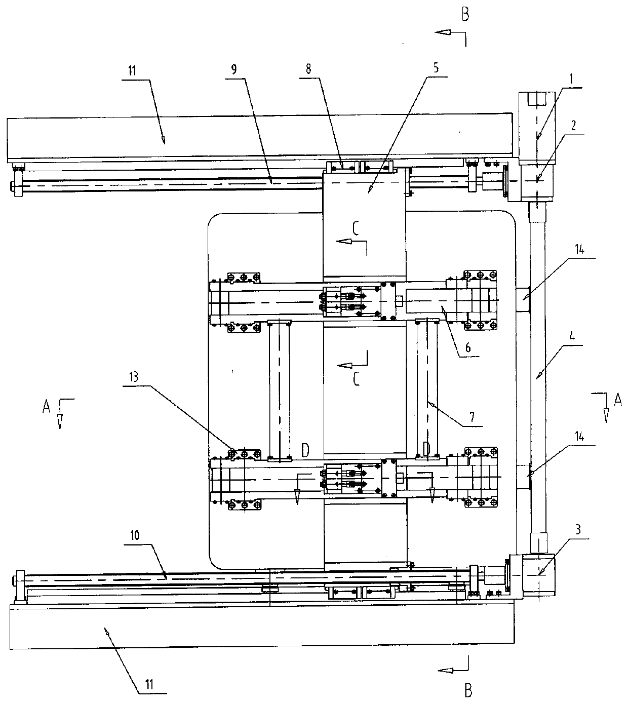
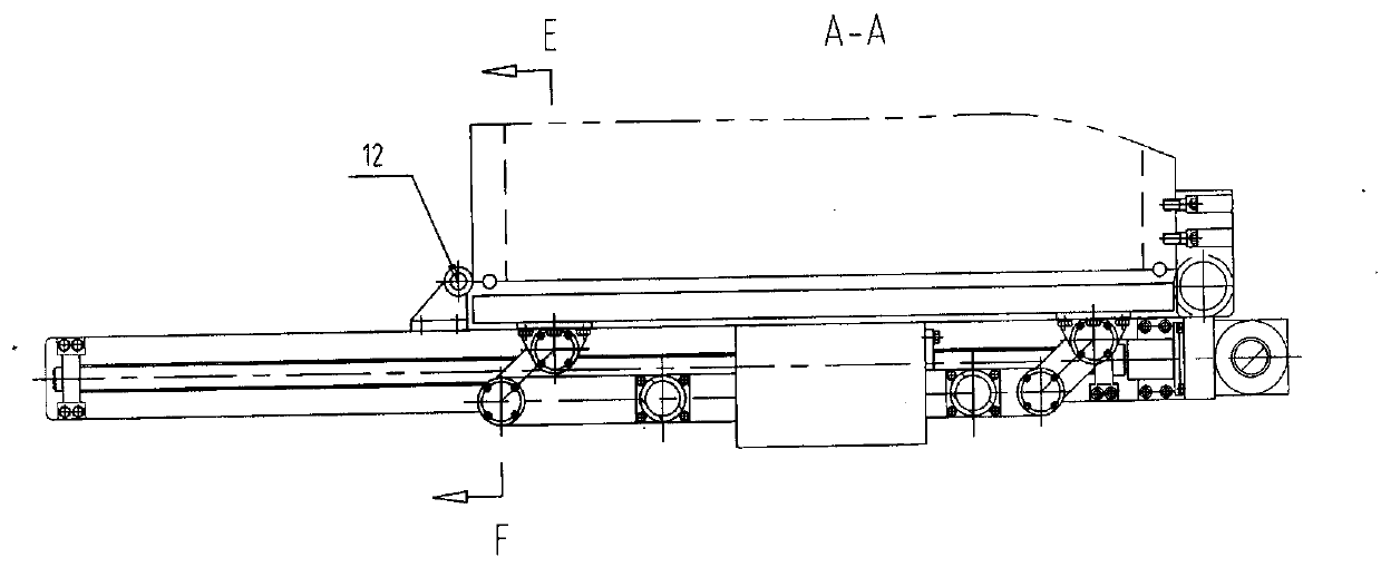
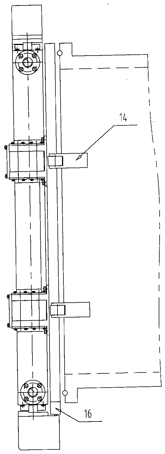
[0022] like figure 1 , 2 , 3, the mechanism of the present invention that can realize automatic door opening and closing and applying a pressing force includes an upper and lower frame 11 installed on the upper and lower sides of the airtight door, a transmission rod 4 driven by the drive unit 1 that is arranged at one end of the frame, The upper and lower commutators 2,3 installed at the two ends of the drive rod 4 are arranged on the upper self-locking screw 9 below the upper frame in a manner parallel to the upper and lower frames, and the lower self-locking screw that is arranged on the lower frame top 10. The power output end of the upper commutator is connected to the upper self-locking screw 9, and the power output end of the lower commutator is connected to the lower self-locking screw 10; synchronously driven by the upper and lower self-locking screws T...


PUM


Abstract

A mechanism capable of realizing automatic door opening and closing and applying a pressing force comprises upper and lower frames, a transmission rod, upper and lower commutators, an upper self-locking lead screw and a lower self-locking lead screw, wherein the upper and lower frames are separately mounted above and under a sealing door; the transmission rod is arranged at one ends of the framesand driven by a driving unit; the upper and lower commutators are mounted at the two ends of the transmission rod; the upper self-locking lead screw is arranged under the upper frame in parallel; thelower self-locking lead screw is arranged above the lower frame; power output ends of the upper and lower commutators are correspondingly connected with the self-locking lead screws in the corresponding positions; the upper and lower ends of a towing frame synchronously driven by the upper and lower self-locking lead screws are correspondingly combined with upper and lower guide rails, which are arranged parallel to the upper and lower frames, in the form of sliding fit; two groups of sliding rods are mounted on the towing frame through upper and lower guide rail pairs which are arranged in parallel; front and rear fixing rods used for realizing synchronous movements of the two groups of sliding rods are arranged between the two groups of sliding rods; the two ends of the sliding rods arecorrespondingly combined with the sealing door through connecting rods and hinge seats; and springs used for compensating moving displacements of the sliding rods are mounted between the sliding rodsand the towing frame.

Description

technical field [0001] The invention relates to the field of vacuum technology, in particular to a mechanism suitable for opening and closing a hermetic door of a large-sized airtight chamber, capable of automatically opening and closing the door and applying a pressing force. Background technique [0002] In the field of vacuum technology, for a large-sized vacuum chamber body, since a large-sized opening flange is required to meet the operation of entering and exiting large-sized materials, it is necessary to install a hermetic door with a relatively large weight and volume. The current conventional design is that the switch of the airtight door is a hinge structure, and the opening and closing of the airtight door requires a relatively large rotating space. In addition, the pressing of the airtight door and the vacuum chamber body requires a large number of pressing screws to be completed by personnel, which is time-consuming, laborious and space-consuming. Contents of t...

Claims


Application Information

Patent Timeline
IPC IPC(8): E05F15/00E06B7/16E06B5/10E06B3/46
Inventor 张磊乐孙志杨卢志辉曹永攀周俊刘岷
Owner ZHENGZHOU RES INST OF MECHANICAL ENG CO LTD
Why Eureka
Try Eureka