Supporting leg hydraulic system and engineering machinery

A hydraulic system and outrigger technology, applied in mechanical equipment, fluid pressure actuating devices, vehicle maintenance, etc., can solve problems such as high ground requirements and inability to perform operations

Inactive Publication Date: 2019-05-17
GUIZHOU JONYANG KINETICS
View PDF7 Cites 2 Cited by
  • Summary
  • Abstract
  • Description
  • Claims
  • Application Information

AI Technical Summary

Problems solved by technology

[0003] Although this kind of outrigger can solve the problem of the supporting force of the car body, it has high requirements on the ground, and the ground must be flat before it can be used. If it encounters narrow or inclined roads, it cannot be operated.

Method used


Image

  • Supporting leg hydraulic system and engineering machinery

Examples


Embodiment 1

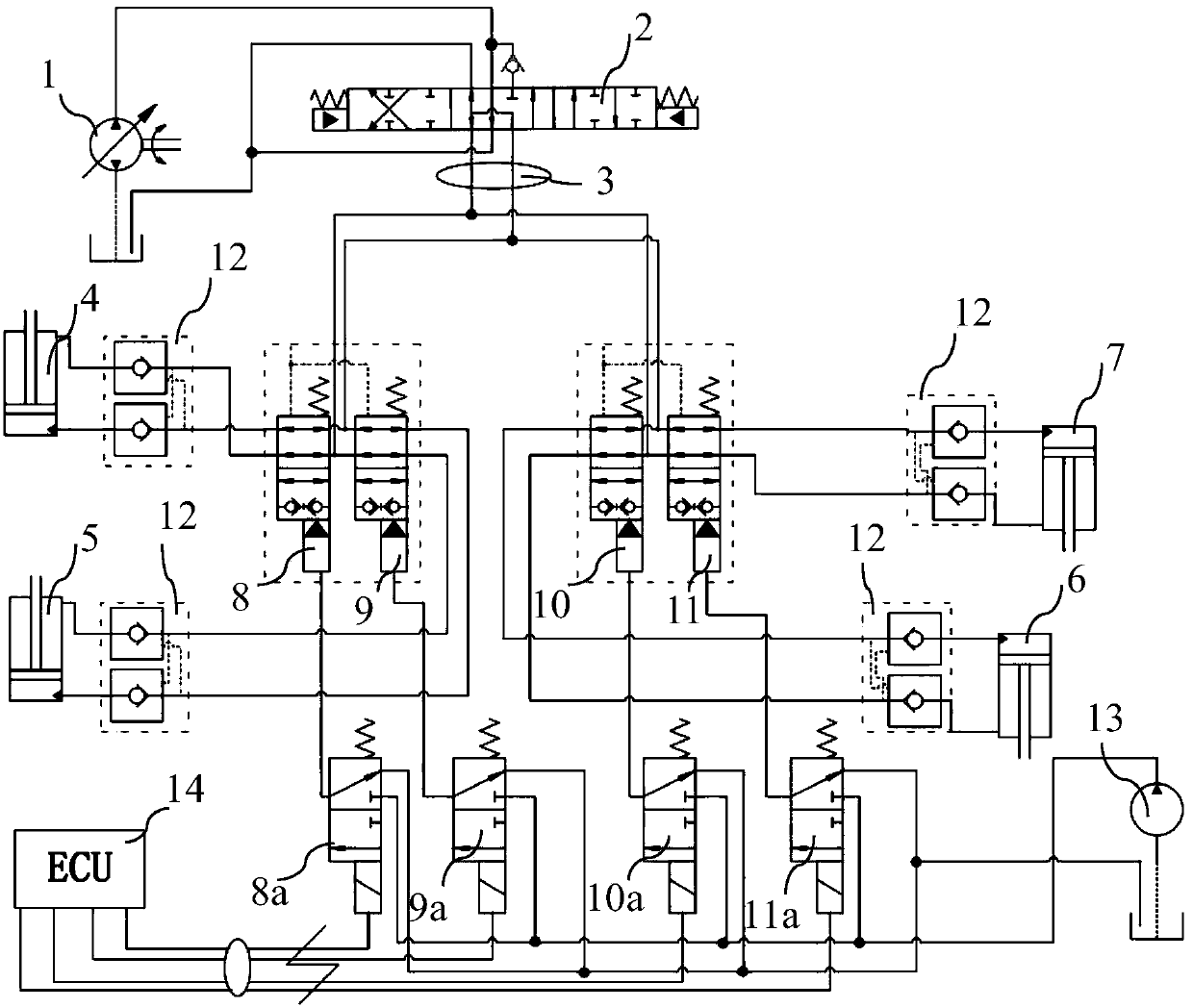
[0032] Please refer to figure 1 , is a schematic diagram of the outrigger hydraulic system according to an embodiment of the present invention.

[0033] In an embodiment of the outrigger hydraulic system disclosed in the present invention, it can be used in excavators, such as figure 1 As shown, it includes a main pump 1, a main valve 2 and four driving cylinders, wherein the main valve 2 is a three-position eight-way electromagnetic reversing valve (it can also be a three-position four-way or a three-position six-way, depending on needs, It is not used to limit the present invention), the four driving cylinders are respectively the first cylinder 4, the second cylinder 5, the third cylinder 6 and the fourth cylinder 7, and the four cylinders can respectively drive a leg to expand and contract.

[0034] After the oil cylinder drives the legs to stretch out, it needs to be maintained to lock the position of the oil cylinder. A hydraulic lock 12 is also installed on the pipelin...

Embodiment 2

[0055] The difference between this embodiment and Embodiment 1 is that the four switching valves are normally open two-position two-way on-off valves, which can be electromagnetic valves or hydraulic control valves, preferably hydraulic control valves. The four on-off valves are respectively Connect to the main oil circuit of four oil cylinders, preferably connect to the main oil circuit of the rod chamber of the four oil cylinders, and directly connect the main oil circuit of the rodless chamber to the main valve 2 through the central rotary joint 3, and the other components remain unchanged.

[0056] In this embodiment, its control principle is similar to that of Embodiment 1, and will not be repeated here.


PUM


Abstract

The invention relates to a supporting leg hydraulic system. The supporting leg hydraulic system is used for controlling stretching and retracting of supporting legs, and comprises a main pump and a main valve connected with a main pump pipeline, and further comprises two or more hydraulic cylinders used for driving the supporting legs to extend and retract correspondingly, a rod cavity oil port and a rodless cavity oil port of each hydraulic cylinder are correspondingly connected into two working oil ports of the main valve in a one-to-one correspondence mode through pipelines, a switching valve capable of being independently controlled is connected into the pipeline between each hydraulic cylinder and the main valve, and each switching valve is controlled so that connection and disconnection of the rod cavity working oil way of the hydraulic cylinder corresponding to the switching valve can be correspondingly controlled. Through the system, free control of extension and retraction ofeach supporting leg can be realized, then the engineering machinery such as a wheel type excavator can be prevented from being limited by the road surface, and the adaptability is stronger. The invention further relates to engineering machinery comprising the supporting leg hydraulic system.

Description

technical field [0001] The disclosed embodiments of the present invention relate to the field of construction machinery, in particular to a hydraulic system for outriggers and construction machinery. Background technique [0002] In the field of construction machinery, many equipment need to use auxiliary outriggers. Taking wheeled excavators as an example, due to the large excavation reaction force generated during operation, the tires, axles and other walking devices are under great force. This not only affects the mechanical strength of the walking device, but also the deformation of the tire will make the work unstable, and the horizontal reaction force is very large, causing the excavator to move forward. In order to make the excavator work stably and reduce the load on the axle, hydraulic outriggers are usually provided on both sides of the frame. Another example is a crane. In order to reduce the stress on the tires and maintain the stability of the car body during o...

Claims


Application Information

Patent Timeline
Patent Type & Authority Applications(China)
IPC IPC(8): F15B11/17F15B13/08B60S9/10
Inventor 冉光宇陈念刘坤陈兆勇
Owner GUIZHOU JONYANG KINETICS
Why Eureka
Try Eureka