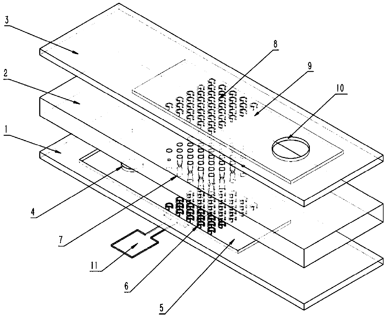
Microchannel heat exchanger structure with spray pipe and work method

A technology of microchannel heat exchanger and tubular structure, which is applied in the direction of heat exchanger type, indirect heat exchanger, heat transfer modification, etc., can solve the problems of limited improvement of heat exchange capacity and difficulty in meeting the heat dissipation requirements of microelectronic devices, etc. To achieve the effect of increasing the disengagement speed, high critical heat flux density, and enhancing heat transfer capacity

Pending Publication Date: 2019-05-17
ENERGY RES INST OF SHANDONG ACAD OF SCI
View PDF7 Cites 4 Cited by
  • Summary
  • Abstract
  • Description
  • Claims
  • Application Information

AI Technical Summary

Problems solved by technology

[0003] Microchannel flow boiling phase transfer heat technology has a very broad application prospect in high heat flux heat dissipation, especially boiling heat transfer in microchannels with micro-fin arrays is a hot spot in the research and application of high heat flux heat dissipation. Some research results have been obtained, but the inventors found that the existing technology mainly uses methods such as changing the shape, size and surface characteristics of the micro-rib array to achieve enhanced heat transfer. need

Method used


Image

  • Microchannel heat exchanger structure with spray pipe and work method
  • Microchannel heat exchanger structure with spray pipe and work method

Examples


Embodiment Construction

[0014] It should be pointed out that the following detailed description is exemplary and intended to provide further explanation to the present application. Unless defined otherwise, all technical and scientific terms used herein have the same meaning as commonly understood by one of ordinary skill in the art to which this application belongs.

[0015] It should be noted that the terminology used here is only for describing specific implementations, and is not intended to limit the exemplary implementations according to the present application. As used herein, unless the context clearly dictates otherwise, the singular is intended to include the plural, and it should also be understood that when the terms "comprising" and / or "comprising" are used in this specification, they mean There are features, steps, operations, means, components and / or combinations thereof.

[0016] For the convenience of description, if the words "up", "down", "left" and "right" appear in the present i...


PUM


Abstract

The invention relates to a microchannel heat exchanger structure with a spray pipe and a work method. The microchannel heat exchanger structure comprises a first heat exchange portion, a second heat exchange portion and at least one spray pipe portion located between the first heat exchange portion and the second heat exchange portion. A high pressure heat exchange flow channel is arranged in thefirst heat exchange portion, a first micro rib array is arranged in the high pressure heat exchange flow channel, a low pressure heat exchange flow channel is arranged in the second heat exchange portion, and the high pressure heat exchange flow channel communicates with the low pressure heat exchange flow channel through at least one spray pipe arranged in the spray pipe portion. The heat exchanger structure is good in heat exchange effect, and can achieve the better heat exchange heat flux.

Description

technical field [0001] The invention relates to the technical field of heat exchange equipment, in particular to a structure and working method of a microchannel heat exchanger with a nozzle. Background technique [0002] In the new generation of electronic chips, high-power laser weapons, radar and nuclear energy and many other military and civilian fields, the heat dissipation heat flux density of some devices has exceeded 1000W / cm 2 , the problem of heat dissipation has become one of the main bottlenecks hindering the development of high-tech such as computer chips to higher performance. If the heat generated by the electronic device cannot be dissipated in time, the temperature of the device will continue to rise, seriously affecting its reliability and service life. Therefore, it is urgent to develop a new high-efficiency strong heat flow cooling technology to obtain greater cooling capacity to meet the urgent needs of heat dissipation for highly integrated and high-po...

Claims


Application Information

Patent Timeline
Patent Type & Authority Applications(China)
IPC IPC(8): F28D15/02
CPCF28F2260/00F28D1/03F28D15/0233F28D2021/0029F28F13/18F28F13/12F28F2245/02F28F2245/04F28D7/1607H01L23/4735
Inventor 段炼刘志刚吕明明贾磊
Owner ENERGY RES INST OF SHANDONG ACAD OF SCI
Why Eureka
Try Eureka