A monitoring system and method for exhaust gas flow rate and particle composition
A monitoring system and gas emission technology, applied in measuring devices, instruments, etc., can solve the problems of inconvenient installation and debugging of instruments, inability to realize comprehensive online monitoring of gas flow rate and particulate matter composition, etc., to avoid the inconvenience of installation and debugging.
- Summary
- Abstract
- Description
- Claims
- Application Information
AI Technical Summary
Problems solved by technology
Method used
Image

Examples
Embodiment 1
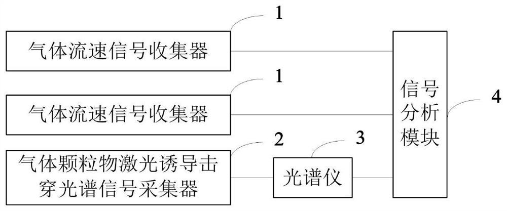
[0044] Embodiment 1 of the present invention provides a monitoring system for exhaust gas flow rate and particle composition.
[0045] Such as figure 1 As shown, the monitoring system includes two gas flow rate signal collectors 1, a gas particle laser-induced breakdown spectrum signal collector 2, a spectrometer 3 and a signal analysis module 4; the two gas flow rate signal collectors 1 along the flue installed in the flue in parallel with the axial direction; each of the gas flow rate signal collectors 1 is installed along the diameter direction of the flue, and the two gas flow rate signal collectors 1 are connected to the signal analysis module 4, and the two The gas flow rate signal collector 1 is used to obtain the flow rate signals of the gas in the two channels of flue, and send the two channels of the flow rate signals to the signal analysis and processing module; The diameter of the flue is installed in the flue, and the gas particle laser-induced breakdown spectrum...
Embodiment 2
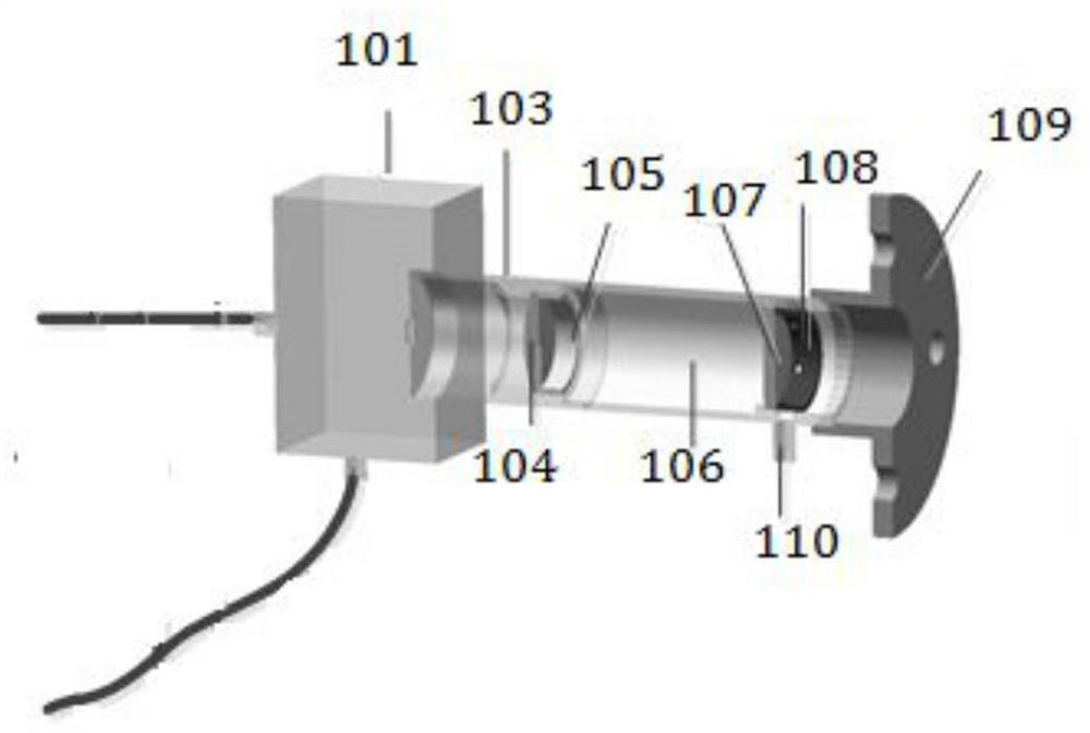
[0048] Embodiment 2 of the present invention is a preferred implementation of a monitoring system for exhaust gas flow rate and particle composition.
[0049] Such as figure 2 As shown, the gas flow rate signal collector 1 includes a detector 101, a detector driving module 102 ( figure 2 Not shown in), mirror frame 103, first signal collection combined lens 104, combined lens pressure ring 105, collimation cavity 106, dustproof mirror 107, dustproof mirror pressure ring 108 and flange 109; the dustproof The mirror 107 is fixed in the collimation cavity 106 through the dust-proof mirror pressure ring 108, and the infrared light emitted by the gas in the flue enters the collimation cavity 106 through the dust-proof mirror 107; the collimation cavity 106 One end of one end is screwed to the flange 109, the other end of the collimation cavity 106 is connected to one end of the mirror frame 103, and the first signal collection combination lens 104 passes through the first signal...
Embodiment 3
[0059] Embodiment 3 of the present invention provides a method for monitoring the flow rate of exhaust gas and the composition of particulate matter.
[0060] Such as Figure 4 As shown, the monitoring method is applied to the monitoring system, and the monitoring method includes the following steps:
[0061] Step 401, obtain two flow velocity signals; step 402, correlate the two flow velocity signals to obtain a correlated signal, and perform online monitoring on the flow velocity of the gas in the flue according to the correlated signal; step 403, obtain the particulate matter laser-induced shock Spectrum signal; step 404, on-line monitoring the composition of the particulate matter in the flue according to the laser-induced breakdown spectrum signal of the particulate matter.
PUM
 Abstract
Description
Claims
Application Information
 - R&D
- Intellectual Property
- Life Sciences
- Materials
- Tech Scout
- Unparalleled Data Quality
- Higher Quality Content
- 60% Fewer Hallucinations
Browse by: Latest US Patents, China's latest patents, Technical Efficacy Thesaurus, Application Domain, Technology Topic, Popular Technical Reports.
© 2025 PatSnap. All rights reserved.Legal|Privacy policy|Modern Slavery Act Transparency Statement|Sitemap|About US| Contact US: help@patsnap.com