[0029] The preferred embodiment of the present invention will be described in detail below.
[0030] The reference signs in the drawings of the specification include:
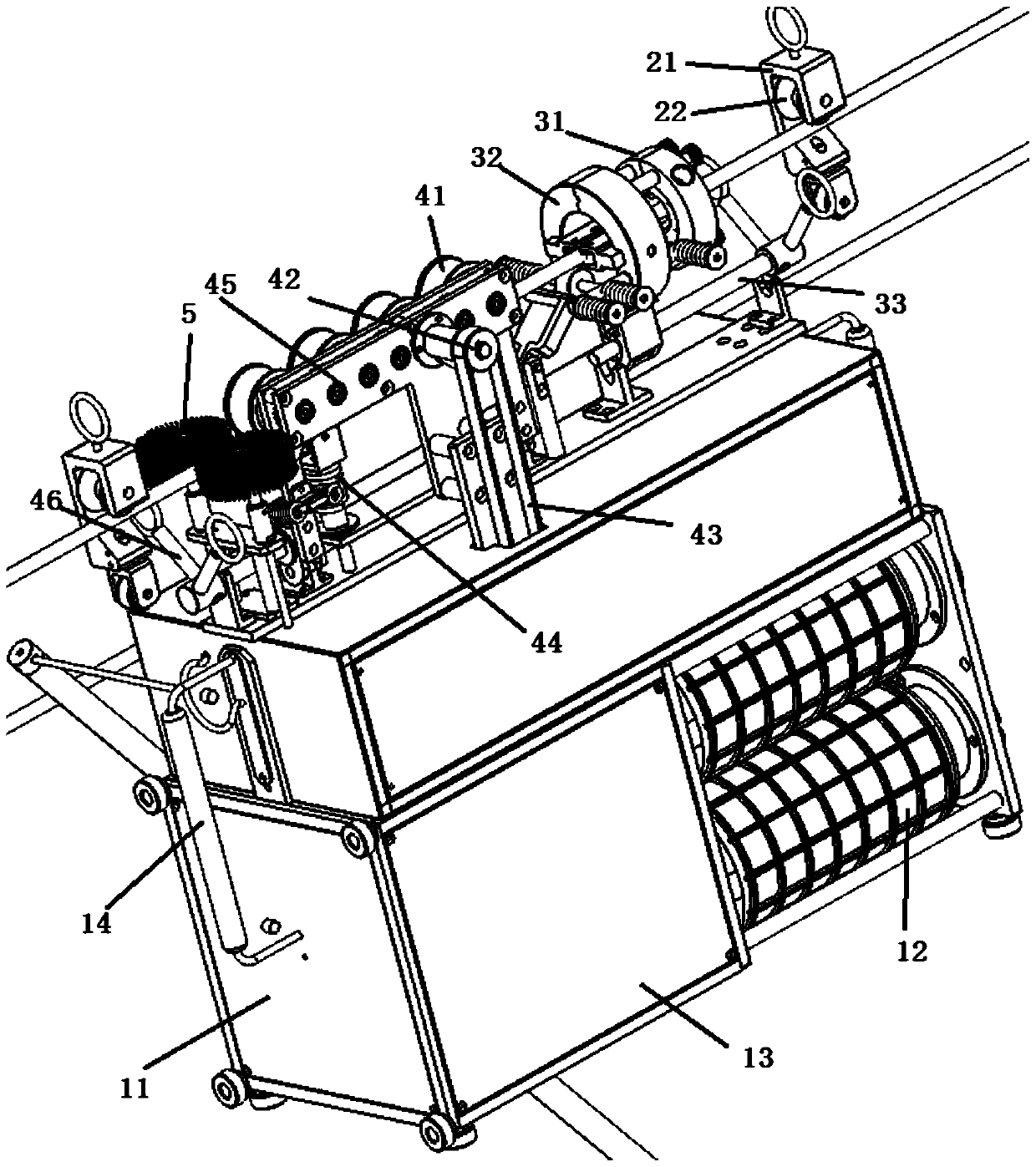
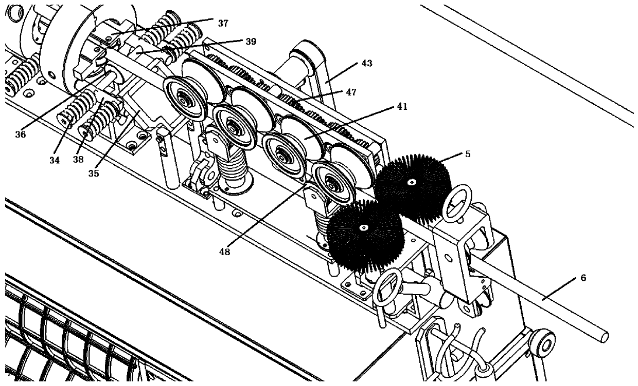
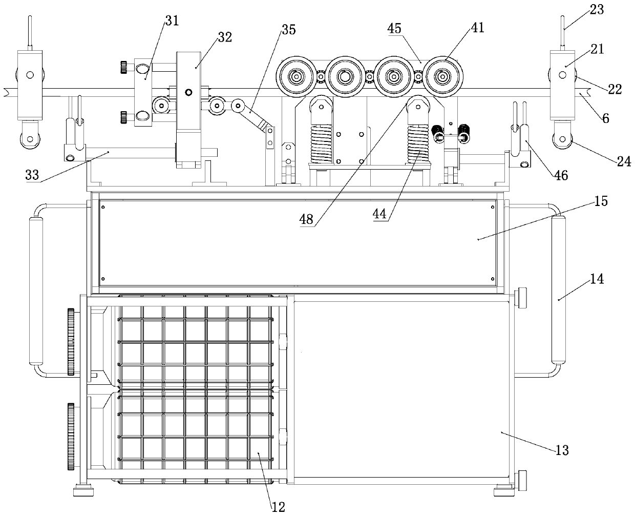
[0031] Cabinet 11, insulating paint bucket 12, sliding door 13, handle 14, motor box 15, locking block 21, third locking wheel 22, suspension ring 23, pulley 24, injection molding pressure ring 31, clamping arm 32, connecting rod 33. The first compression spring 34, the rotating arm 35, the first roller 36, the clamping block 37, the fixed rod 38, the pressure rod 39, the second retaining wheel 41, the driven wheel 42, the conveyor belt 43, the second compression spring 44, The clamping plate 45, the second rocking handle 46, the gear 47, the second roller 48, the cleaning brush 5, and the bare wire 6.
[0032] Such as Figure 1~3 The intelligent encapsulating and spraying robot for high-voltage live overhead bare wires includes a cabinet 11, a suspension device for suspending the bare wires 6, a glue injection device for encapsulating the bare wires 6, and a transmission device for transferring the bare wires 6 ;
[0033] The cabinet 11 is divided into upper and lower sides. The upper layer of the cabinet 11 is a motor box 15 where a rotating motor is placed. The rotating motor provides power for the walking of the rubber-coated robot. The lower layer of the cabinet 11 is a sliding cabinet with a sliding door 13 installed on the front side. In the sliding cabinet is placed an insulating paint bucket 12, an air pressure tank connected to the insulating paint bucket 12, and a hose connected to the injection hole. The air pressure tank is opposite to the insulating paint bucket. 12 Inflate, and the insulating paint in the insulating paint bucket 12 is extruded from the injection hole on the glue injection device through a hose, and is evenly coated on the surface of the bare wire 6 to realize the encapsulation of the bare wire 6. A handle 14 is installed on the outside of the cabinet 11 to facilitate the operator to move the cabinet 11.
[0034] The suspension device is in the shape of a keychain, similar to the principle of a keychain. The suspension device includes a locking block 21, a third locking wheel 22 installed on the locking block 21, and a suspension ring 23 fixedly installed on the upper end of the locking block 21, The overhead transmission line for fixing the bare conductor 6 is passed through the suspension ring 23, the lower end of the block 21 is fixedly installed with a pulley 24, and a pull rope is passed through the pulley 24. One end of the pull rope is fixed on the handle 14 of the cabinet 11. The rope transmits the cabinet 11 and the transmission device and the glue injection device on the cabinet 11 to the vicinity of the bare wire 6. The upper end of the retaining block 21 is inverted U-shaped and the lower end is L-shaped. The lower end of the retaining block 21 is hinged with an elastic piece. The third retaining wheel 22 is fixedly installed on the inner side of the retaining block 21. The rotating shaft where the elastic piece connects with the retaining block 21 The upper sleeve is covered with a torsion spring, which is similar to the principle of automatic door closing. After the bare wire 6 is pressed into the groove of the third retaining wheel 22 along the shrapnel, the shrapnel automatically returns to its original position under the action of the torsion spring to realize the shrapnel and the retaining block 21 的locking.
[0035] The glue injection device includes a fixed seat with an open lower part and an open upper part, an arc-shaped clamping arm 32 fixedly installed on both sides of the fixed seat, and an arc-shaped injection molding pressure ring 31 fixedly connected with the clamping arm 32. The clamping arm 32 and the upper part of the corresponding injection molding pressure ring 31 are fixedly connected by fasteners, which are bolts. The fixed connection between the corresponding clamping arm 32 and the injection molding pressure ring 31 is achieved by bolt fasteners.
[0036] The inner side of the clamping arm 32 is respectively fixedly installed with clamping blocks 37 with grooves in the middle; the grooves of the clamping blocks 37 are evenly fixedly installed with a number of first retaining wheels, and the first retaining wheels are provided with bare wires for convenience 6 through the limit slot, the middle part of the pressing rod 39 is rotatably installed with a first roller 36 which is convenient for the transmission of the bare wire 6. The first retaining wheel and the first roller 36 play a role of limiting the bare wire 6. The clamping arm 32 and the lower part of the corresponding injection pressure ring 31 are fixedly installed with a fixing rod 38 passing through the clamping arm 32, and a set of pressure rods are fixed on the fixing rod 38 between the clamping arm 32 and the injection pressure ring 31. 39. Two sets of pressure rods 39 are provided on the fixed rod 38 outside the clamping arm 32. The free end of the pressure rod 39 is fixedly installed with a limit seat, and the pressure rod 39 between the limit seat and the corresponding fixed rod 38 is sleeved with a first pressure spring 34, which helps the clamping arm 32 return Bit. The first roller 36 is arranged on the pressing rod 39 on both sides of the clamping arm 32, and the first roller 36 facilitates the transmission of the bare wire 6.
[0037] Four injection holes are evenly opened on the injection pressure ring 31, and the injection holes are connected to the insulating paint bucket 12 in the cabinet 11 through a hose. A through hole is opened in the middle of the fixing seat, and a first cam is movably installed in the through hole. A connecting rod 33 is fixedly installed on the first cam. The aspect ratio of the first cam is different. The connecting rod 33 and the first cam are integrally formed. The connecting rod 33 drives the first cam to rotate to realize the opening and closing of the fixing seat, thereby realizing the opening and closing of the clamping arm 32 and the injection molding pressure ring 31, and clamps the bare wire 6 to be encapsulated in the clamping arm 32 And injection molding pressure ring 31. The free end of the connecting rod 33 is fixedly installed with two first rocking handles, the angle between the two first rocking handles is 30-60°, and the free end of the first rocking handle is integrally formed with a first ring. The operator A suitable drawstring is inserted into the first loop, and the clamping arm 32 can be opened and closed by pulling the drawstring, eliminating the need for the operator to climb and install the bare wire 6 to pull the glue injection device.
[0038] The transmission device includes two locating plates 45 fixedly connected. The four corners of the two locating plates 45 are fixedly connected by fixed posts. The two outer sides of the locating plate 45 are respectively fixedly installed with a driven wheel 42 and a plurality of second locating wheels. 41. A driving wheel is fixedly installed on the rotating motor, a conveyor belt 43 is installed between the driving wheel and the driven wheel 42, a number of meshing gears 47 are evenly installed between the two retaining plates 45, and the second retaining wheel 41 is fixedly connected On the rotating shaft of the interphase gear 47, the driven wheel 42 is fixedly connected with one of the gears 47 through the rotating shaft, and the driving wheel is driven to rotate by the rotating motor, thereby driving the driven wheel 42 and the gear 47 coaxially connected with the driven wheel 42 to rotate, thereby realizing transmission The device drives the glue injection device, the rotating device and the cabinet 11 to move along the line. Two limit posts are fixedly installed on the cabinet 11 below the second retaining wheel 41, a second compression spring 44 is sleeved on the limit posts, and the upper end of the limit post is fixedly installed with a card slot, and a second roller 48 is installed in the card slot. The cooperation of the second retaining wheel 41 and the second roller 48 realizes the fixation of the bare wire 6. The lower part of the locking plate 45 is fixedly connected with an open base, the middle of the base is provided with a through hole, and a second cam is movably installed in the through hole. A connecting rod 33 is fixedly mounted on the second cam. The diameter ratio is different, and the connecting rod 33 is integrally formed with the second cam. The connecting rod 33 drives the second cam to rotate to realize the opening and closing of the base, thereby facilitating the clamping of the bare wire 6 between the second retaining wheel 41 and the second roller 48 through the second compression spring 44 on the limiting post The elastic effect of the, the bare wire 6 can be clamped more stably. Two second rocking handles 46 are fixedly installed on the free end of the connecting rod 33. The angle between the two second rocking handles 46 is 30-60°. The free end of the second rocking handle 46 is integrally formed with a second loop, and the operator inserts a suitable drawstring into the second loop, and passes Pulling the rope can turn the locking plate 45 outwards to a certain angle, so that the bare wire 6 can be inserted between the second locking wheel 41 and the second roller 48 of the locking plate 45. Pull the second ring in the opposite direction to The clamping plate 45 is buckled on the limit post.
[0039] A column is fixedly installed on the cabinet 11 between the glue injection device and the transmission device, and a rotating arm 35 fixedly connected to the glue injection device is hinged on the column. The angle between the glue injection device and the transmission device can be adjusted by the rotating arm 35.
[0040] It also includes a number of cleaning brushes 5. The cleaning brush 5 is arranged on the outside of the transmission device opposite to the glue injection device. The cleaning brush 5 can clean up the garbage and dirt on the bare wire 6 before encapsulation, and further improve the packaging of the bare wire 6. Glue effect.
[0041] When the high-voltage charged overhead bare wire intelligent rubber coating and spraying robot works, the whole rubber coating robot is first suspended on the overhead transmission line through a suspension device, and the first rocker on the glue injection device is pulled to connect the clamping arm 32 and the injection pressure ring 31 is opened, the bare wire 6 to be coated is clamped in the first clamping wheel of the clamping block 37 between the clamping arms 32, and the first rocking handle on the glue injection device is reversely pulled to connect the clamping arm 32 and The injection molding pressure ring 31 is closed to realize the pre-positioning of the bare wire 6 to be encapsulated. The bare wire 6 is limited between the first retaining wheel and the first roller 36; in the same way, by pulling the second rocking handle on the transmission device, The clamping plate 45 rotates to one side of the bare wire 6 to be encapsulated, and the bare wire 6 to be encapsulated is placed on the second roller 48 on the limit post, and the second rocking handle on the transmission device is reversely pulled to lock the position The second retaining wheel 41 on the board 45 is clamped on the bare wire 6 to be encapsulated to realize the positioning of the transmission device and the bare wire 6 to be encapsulated. The bare wire 6 is limited to the second retaining wheel 41 and the second roller 48 In between, the rotating motor drives the driven wheel 42 to rotate through the conveyor belt 43, which in turn drives the gear 47 coaxial with the driven wheel 42 to rotate. Since the second retaining wheel 41 is fixedly connected to the shaft of the interphase gear 47, the direction of rotation of the interphase gear 47 In the same way, the second retaining wheel 41 is driven to rotate in the same direction to realize that the transmission device pulls the bare wire 6 forward, so that the glue injection device connected to the transmission device can evenly coat the bare wire 6 to be coated. The intelligent encapsulating robot for live overhead bare wires 6 can realize the positioning and traction of the bare wires 6 by the operator on the ground. At the same time, due to the close cooperation between the transmission device and the glue injection device, the fixing effect and the encapsulating effect of the bare wires 6 are obtained. Greatly improved.
[0042] Finally, it should be noted that the above preferred embodiments are only used to illustrate the technical solutions of the present invention and not to limit it. Although the present invention has been described in detail through the above preferred embodiments, those skilled in the art should understand that it can be combined in form and Various changes are made to the details without departing from the scope defined by the claims of the present invention.