Vibration reduction mechanism of stator winding machine

A vibration damping mechanism and stator winding technology, applied in electromechanical devices, manufacturing motor generators, electrical components, etc., can solve the problems of speeding up parts, damage, impact winding machines, etc., and achieve the effect of reducing vibration

Pending Publication Date: 2019-05-17
ZTD TECH IND QINGDAO CO LTD
View PDF2 Cites 1 Cited by
  • Summary
  • Abstract
  • Description
  • Claims
  • Application Information

AI Technical Summary

Problems solved by technology

[0005] In view of the transmission mode of the eccentric wheel in the prior art, the entire driving mechanism will generate strong vibration during the high-speed reciprocating motion, the vibration will impact the entire winding machine, generate noise and accelerate the damage of parts, etc., and provide a The vibration damping mechanism of the stator winding machine adopts the way of setting two sets of flying fork rod drive components symmetrically, which provides a new way of thinking for the vibration and noise reduction of the stator winding machine

Method used


Image

  • Vibration reduction mechanism of stator winding machine
  • Vibration reduction mechanism of stator winding machine
  • Vibration reduction mechanism of stator winding machine

Examples


Embodiment Construction

[0041] The technical solutions of the present invention will be further described below in conjunction with the accompanying drawings in the embodiments of the present invention.

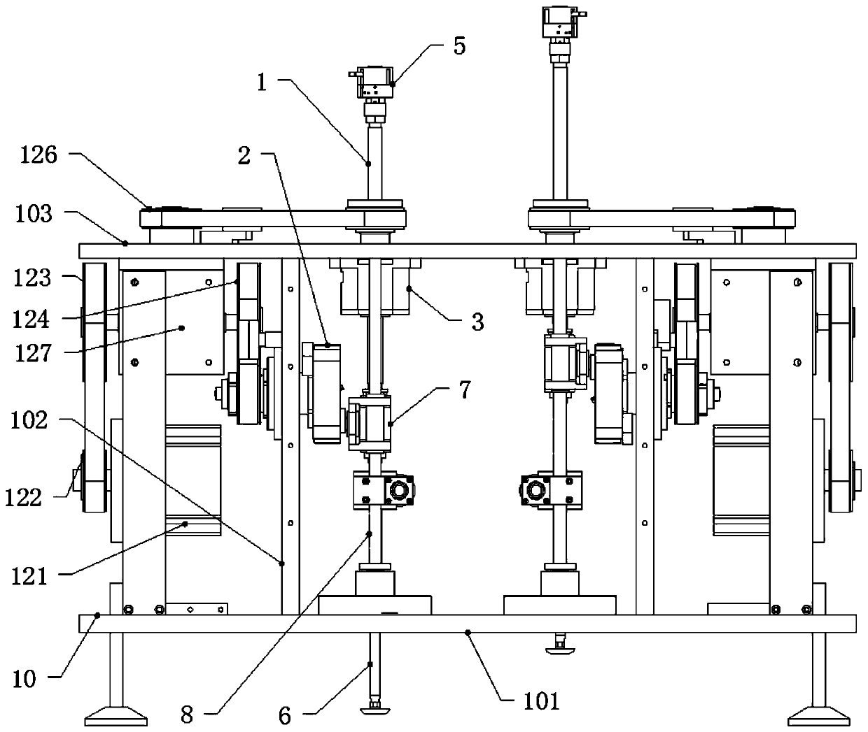
[0042] A vibration damping mechanism of a stator winding machine, comprising a frame 10 and a winding drive mechanism,

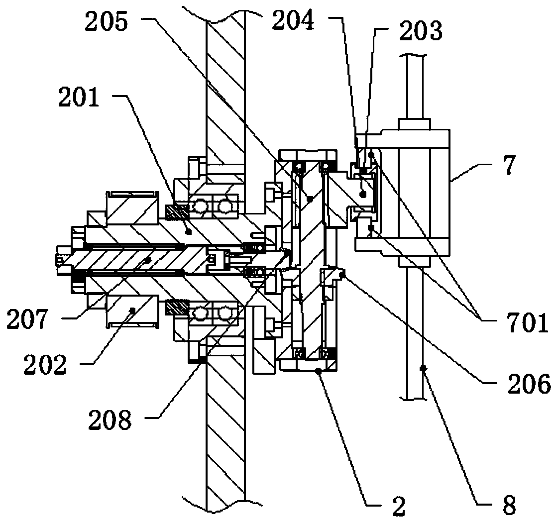
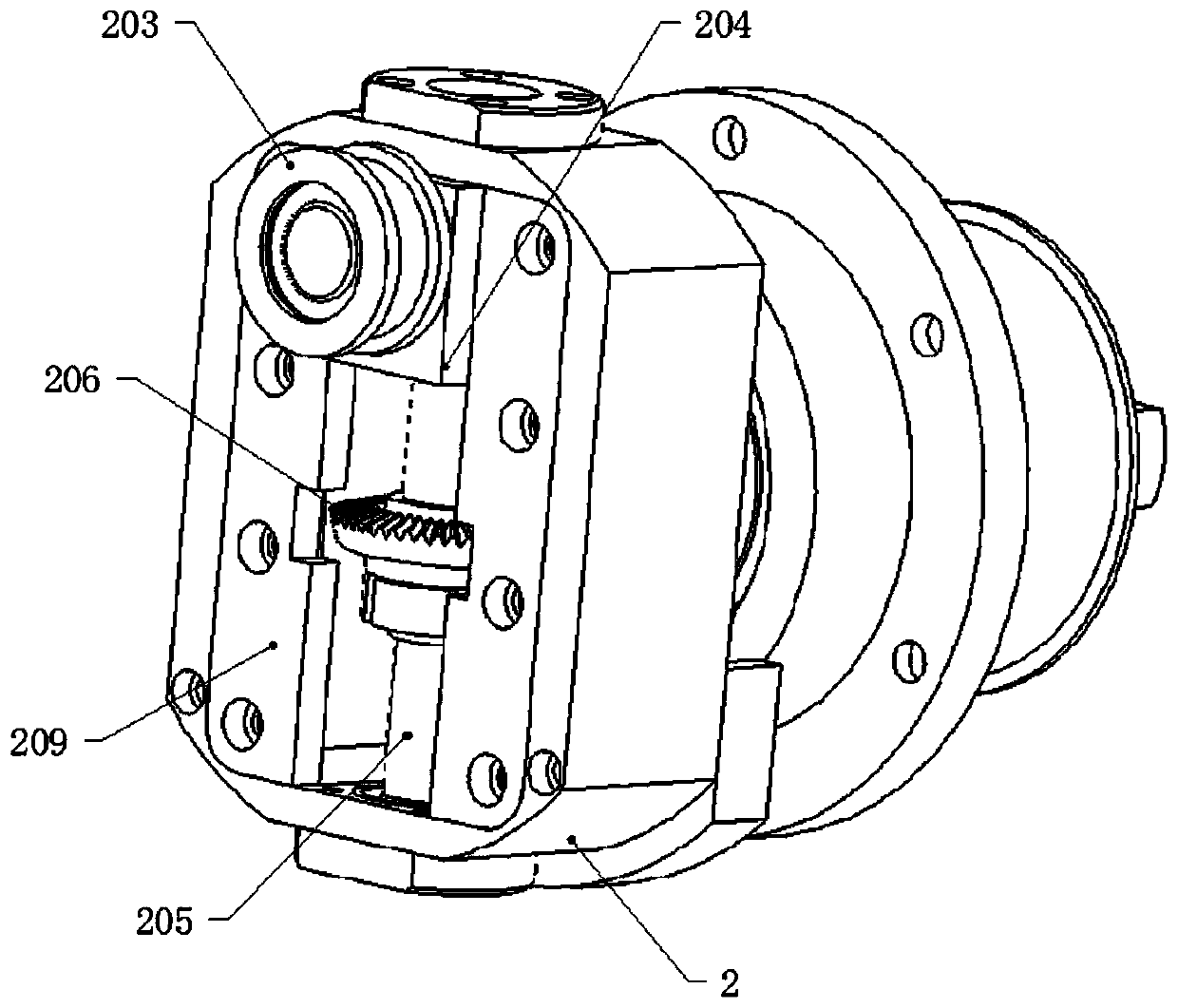
[0043] Described winding drive mechanism comprises power source, upper fly fork lever 1, cam 2, slide block 7, winding head 5 and guide rod 8, and described guide rod 8 is vertically arranged on the frame 10, and described slide block 7 Set on the guide rod 8, the cam 2 is rotatably connected to the frame 10 and driven by a power source to rotate, the cam 2 is connected to the slider 7 through cam transmission, and the slider 7 is driven up and down along the guide rod 8 during the rotation of the cam 2 Sliding, the upper flying fork lever 1 is provided with a winding head 5, the lower end is connected with the slider 7, and the middle part is slidably connected with the frame 10,...


PUM


Abstract

The invention discloses a vibration reduction mechanism of a stator winding machine. The vibration reduction mechanism comprises a rack and two winding driving mechanisms. Each winding driving mechanism comprises a power source, an upper flying fork rod, a cam, a sliding block, a winding head and a guide rod, wherein the guide rod is vertically arranged on the rack, the sliding block is installedon the guide rod in a sleeving mode, the cam is rotationally connected to the rack and is driven by the power source to rotate, the winding head is arranged on the upper flying fork rod, the lower endof the upper flying fork rod is connected with the sliding block, and the middle of the upper flying fork rod is connected with the rack in a sliding mode. According to the two winding driving mechanisms, the cams of the two winding driving mechanisms rotate periodically with a degree difference on phase in the working process. The vibration reduction mechanism has the advantages that since the two winding driving mechanisms are arranged at the left and the right of the rack respectively, the cams of the two winding driving mechanisms rotate periodically with the degree difference of 180 degrees on phase in the winding working process, in this way, inertia forces of up-and-down motion of the two groups are mutually offset, consequently, vibration of the winding machine is reduced, and theeffects of reducing vibration and lowering noise are achieved.

Description

technical field [0001] The invention belongs to the technical field of motor stator winding machines, and in particular relates to a vibration-damping driving system of a winding machine. Background technique [0002] In the stator production process of the motor, a stator winding machine is needed to wind the copper wire on the stator to form a winding. The stator winding machine generally adopts the combination mechanism of power source, eccentric wheel, guide rod, sliding rod and fly fork rod. The transmission mode of the eccentric wheel makes the whole driving mechanism generate strong vibration during high-speed reciprocating motion. Vibration will impact the entire winding machine, generate noise, and accelerate component damage and many other problems. [0003] The invention patent with the authorized notification number CN105406639B discloses a numerical control follow-up lifting system, which uses a numerical control drive system to replace the drive mechanism of t...

Claims


Application Information

Patent Timeline
Patent Type & Authority Applications(China)
IPC IPC(8): H02K15/08F16F15/22
Inventor 申保玲任培玉曲铭华李学强
Owner ZTD TECH IND QINGDAO CO LTD
Why Eureka
Try Eureka