Switch fitting

A technology for switching devices and switching shafts, applied in valve devices, cocks including cut-off devices, valve details, etc., can solve problems such as large torque and achieve reliable sealing.

Inactive Publication Date: 2003-01-01
プファンネンシュミットゲーエムベーハー
View PDF7 Cites 4 Cited by
  • Summary
  • Abstract
  • Description
  • Claims
  • Application Information

AI Technical Summary

Problems solved by technology

This known design requires high torques during operation and during installation of the aforementioned switch shaft

Method used


Image

  • Switch fitting
  • Switch fitting
  • Switch fitting

Examples


Embodiment Construction

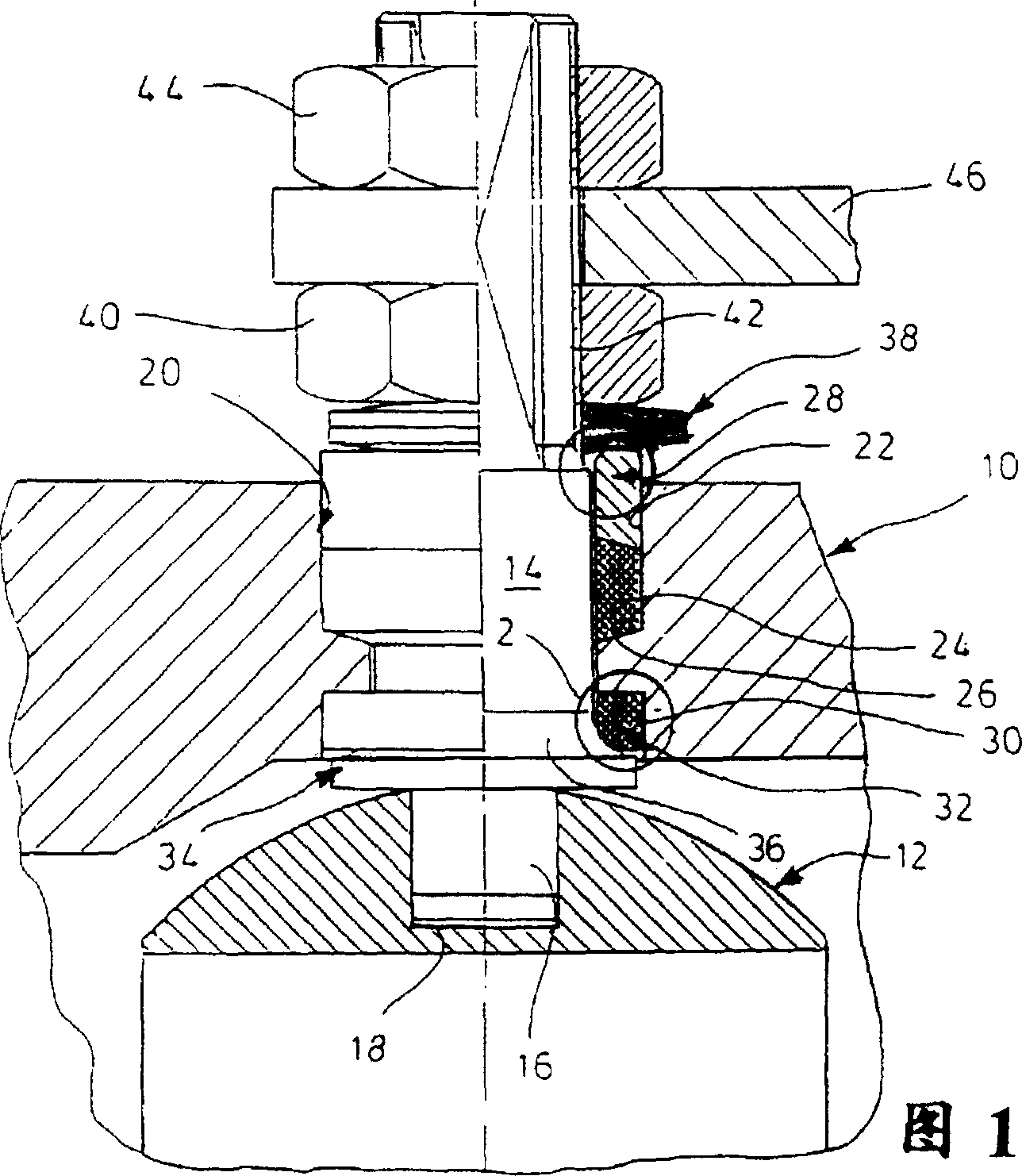
[0026]In FIG. 1 , the valve chamber 10 of a float valve has a spherical valve plug 12 which is rotatable by means of a switching shaft 14 because the journal 16 fits in a suitable recess 18 .

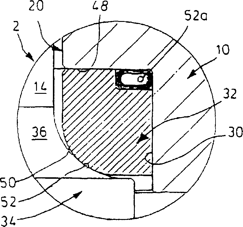
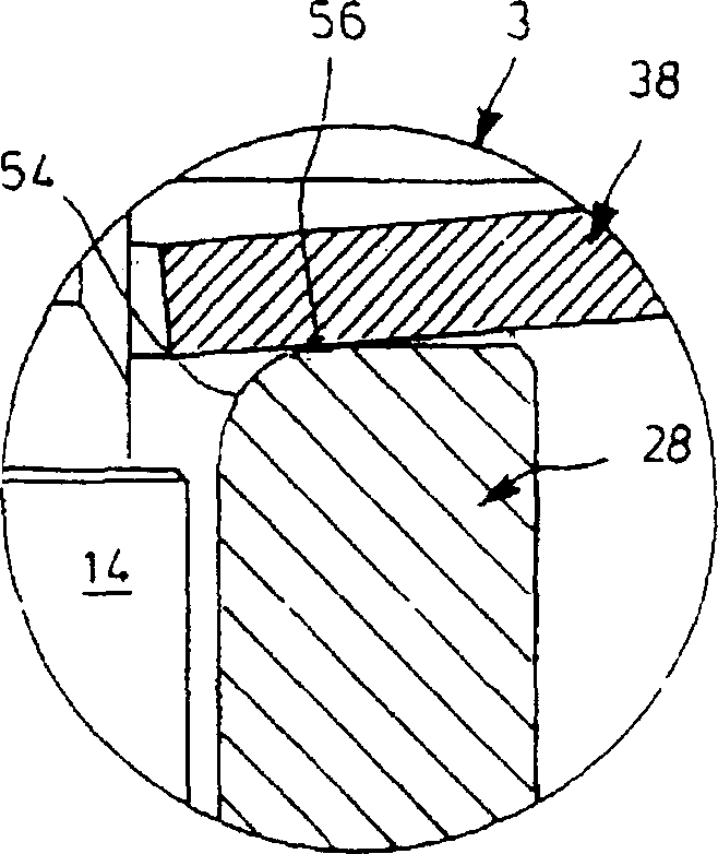
[0027] The valve chamber 10 includes a bore 20 , in a first bore section 22 of which a sleeve-shaped seal 24 is arranged. By reducing the diameter of bore 22 , a shoulder 26 extending obliquely downward relative to bore 20 is formed for supporting seal 24 . The upper side of the seal 24 is also provided with a sloped surface which fits the sloped surface of a compression ring 28 suitably mounted in the bore section 22 . A sealing ring 32 is provided in the lower section 30 of the bore, the details of which will be described later. This seal cooperates with a radial shoulder 34 of the switch shaft 14 , which has a concavely curved spherical sealing surface 36 .

[0028] Above the compression ring 28 is provided a spring assembly 38 consisting of two disc springs which can be adjusted b...


PUM


Abstract

Switch fitting, in particular a cock, ball cock, flap or likewise, with a switch rod for a switch member, which is rotatably and slightly tiltably guided in a switch shaft bore of a fitting housing and which has a sealing surface which is formed on a collar on the side opposed to the switch member, with a sealing ring cooperating with the sealing surface and being supported on a graduation of the switch shaft bore, and with a spring pressing the sealing surface against the sealing ring, wherein the sealing ring has essentially a line contact with the sealing surface.

Description

technical field [0001] The invention relates to a switching device with a switching shaft for a switching element, which is rotatably mounted and slightly pivotable in a shaft bore of a housing, the shaft having a sealing surface, a sealing ring with the The sealing surfaces cooperate and are sealingly supported on a step of the shaft bore of the housing, the sealing surfaces and the sealing ring being elastically pressed towards each other by spring means. Background technique [0002] The sealing of the switch shaft relative to its device housing is critical due to the possibility of leakage, especially when the switch shaft is turned by means of a single-sided handle. This is because the above-mentioned operation produces a tilting moment on the switch shaft, which on the one hand presses the sealing rings together and on the other hand allows a gap to form. [0003] Patent DE-U-78 15061 discloses a switching device, the switching shaft of which is fixed in the device ho...

Claims


Application Information

Patent Timeline
Patent Type & Authority Patents(China)
IPC IPC(8): F16K5/06F16K41/02
CPCF16K5/0694F16K41/026
Inventor 艾哈德·普法嫩施密特
Owner プファンネンシュミットゲーエムベーハー
Why Eureka
Try Eureka