Electromechanically controlled 3D camera with crossed light paths

A camera and optical path technology, applied in the field of electromechanically controlled cross optical path 3D cameras, can solve the problem that the microscope does not have zoom and focus functions, and achieve the effect of comfortable observation and real and clear 3D images

Active Publication Date: 2019-05-21
濮阳市润源医用品有限公司
View PDF10 Cites 0 Cited by
  • Summary
  • Abstract
  • Description
  • Claims
  • Application Information

AI Technical Summary

Problems solved by technology

[0004] The purpose of the present invention is to provide a 3D camera with electromechanical control crossed optical paths, to solve the above-mentioned background technology, the pure optical surgical microscopes with small objective lens structure do not have zoom and focus functions, and the pupils only operate on the microscope eyepieces for a long time. It is an unbearable problem for ordinary people

Method used


Image

  • Electromechanically controlled 3D camera with crossed light paths
  • Electromechanically controlled 3D camera with crossed light paths
  • Electromechanically controlled 3D camera with crossed light paths

Examples


Embodiment 1

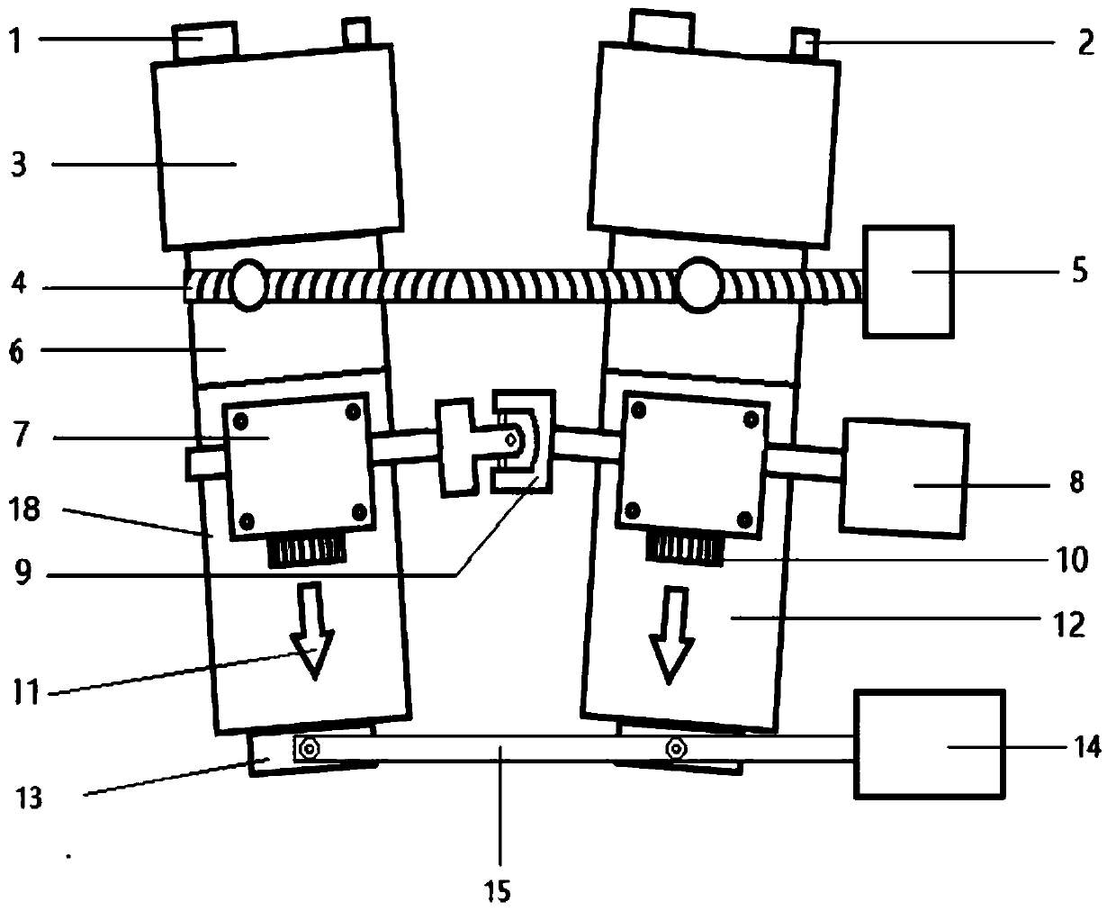
[0023] An electronically controlled cross-optical 3D camera, such as figure 1 As shown, it includes two lens barrels 18 installed in parallel. The top of each lens barrel 18 is equipped with an optoelectronic sensor 3. The top of the optoelectronic sensor 3 is provided with an optoelectronic sensor output port 1 and an optoelectronic sensor power input port 2. The rotation adjustment ring on the outer wall of the barrel 18 is connected by a variable optic chiasm linkage rod 4. One end of the variable optic chiasm linkage rod 4 is provided with an optic chiasm linkage power device 5, and the middle of the outer walls of the two lens barrels 18 are respectively provided with The steering gears 7 are equipped with a zoom gear 10 at the bottom of each steering gear 7, and guide laser lights 11 are also provided on the outer walls of the two lens barrels 18. The two steering gears 7 are connected by a zoom universal coupling 9, and the zoom universal A zoom power device 8 is connecte...

Embodiment 2

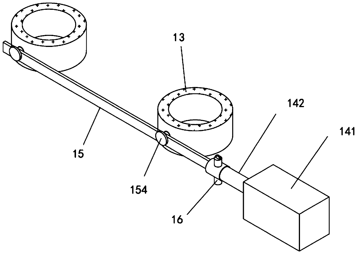
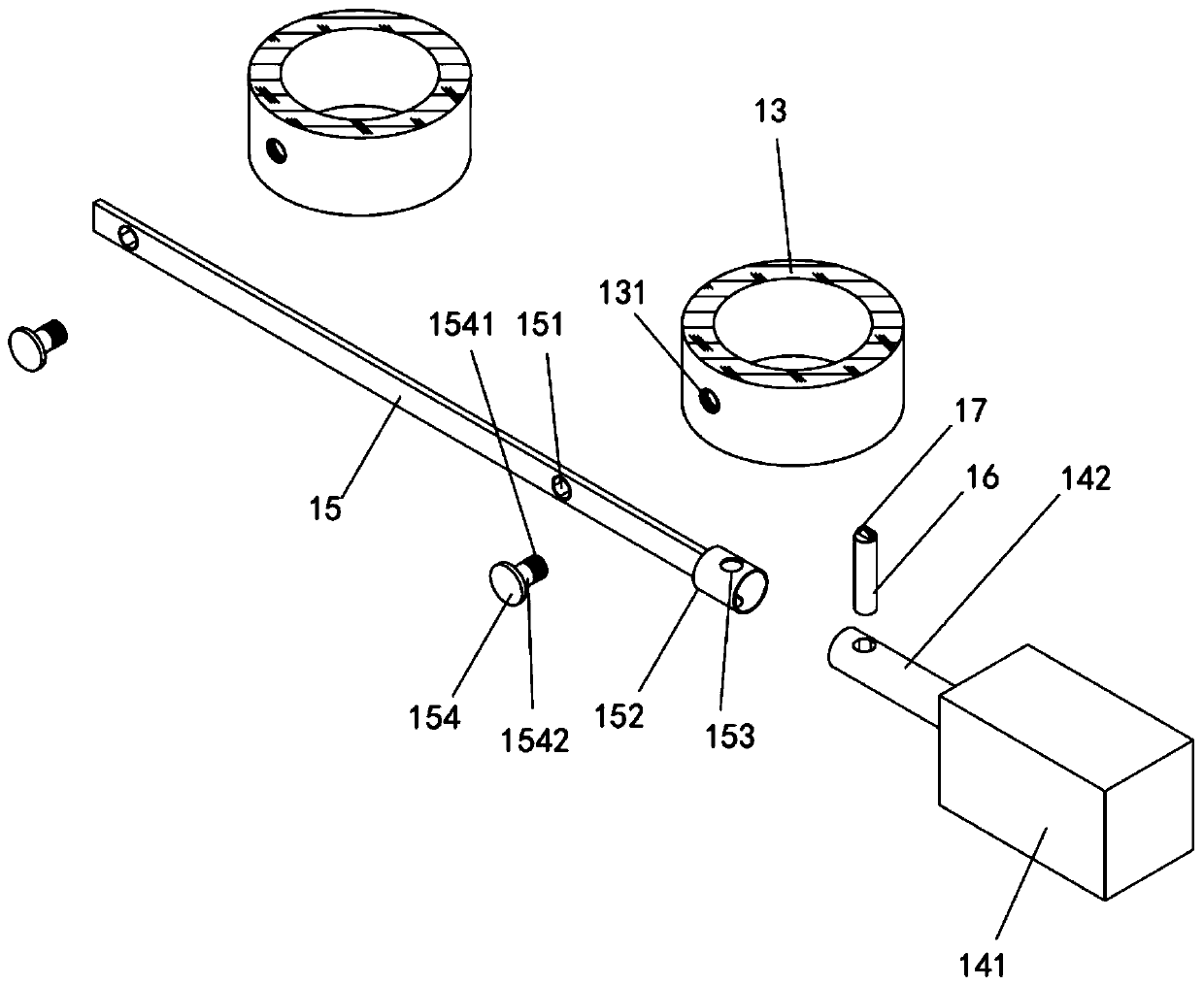
[0027] As the second embodiment of the present invention, such as figure 2 with image 3 As shown, the optic cross connecting rod power unit 5, the zoom power unit 8 and the focus power unit 14 all include a cylinder 141, and the cylinder 141 is provided with a piston rod 142.

[0028] Further, the focus linkage rod 15 is provided with two rotating holes 151, and the distance between the two rotation holes 151 is adapted to the distance between the two objective lenses 13. The focus linkage rod 15 is close to the focus power device 14 One end is provided with a fixed sleeve 152, the fixed sleeve 152 and the focusing linkage rod 15 are integrally formed, the fixed sleeve 152 is provided with a fixed hole 153, the outer wall of the objective lens 13 is provided with a screw hole 131, and the piston rod 142 is far away A fixing hole 153 is also opened on the circumferential surface of one end of the cylinder 141, and the piston rod 142 and the fixing sleeve 152 are inserted and fit...


PUM


Abstract

The invention relates to the technical field of mechanical preparation, in particular to an electromechanically controlled 3D camera with crossed light paths. The electromechanically controlled 3D camera comprises two lens cones mounted in parallel, rotary adjuring rings of the two lens cones are connected through a variable optic chiasma linkage rod, an optic chiasma linkage power device is arranged at one end of the variable optic chiasma linkage rod, two steering gears are connected through a zooming universal coupler, and a zooming power device is arranged at one end of the zooming universal coupler. Electronic ocular lenses are mounted at the inner tops of the two lens cones, objective lenses are mounted at the bottoms of the two lens cones, and the two objective lenses are connectedthrough a focusing linkage rod. One end of the focusing linkage rod is connected with a focusing power device. According to the electromechanically controlled 3D camera, optical ocular lens is not needed, a doctor can carry out observation for a long time without focusing the two eyes on optical openings of the ocular lenses, and the doctor is more comfortable during observation. The lens cones and a sensor are straightly mounted, so that the objective lenses, a zooming device, an electronic ocular lens adaption device and the sensor are coaxially and linearly arranged, and a 3D image is moretrue and clear.

Description

Technical field [0001] The invention relates to the technical field of mechanical equipment, in particular to an electromechanically controlled cross-optical 3D camera. Background technique [0002] In order to perform the operation accurately in the surgical operation, a surgical microscope is used to realize the magnified view of the 3D stereoscopic image. The principle of 3D stereo vision is that binocular vision comes from images in different directions from left to right. 3D stereo vision is formed by the visual integration of the brain. At present, the two optical barrels of surgical microscopes are generally installed in parallel. In order to make the two images overlap, a large objective lens is often used to refraction to form an angle of vision. The structure is complicated and it also has a certain impact on the image quality. At present, there are also pure optical surgical microscopes with a small objective lens structure, but they do not have zoom and focus functi...

Claims


Application Information

Patent Timeline
IPC IPC(8): A61B90/20G02B21/36
Inventor 耿孟录
Owner 濮阳市润源医用品有限公司
Why Eureka
Try Eureka