Cogging mill of high-strength deformed steel bars

A technology of rebar and blanking machine, which is applied in the direction of metal rolling stand, metal rolling mill stand, metal rolling, etc., can solve the problems of increasing the blanking machine and reducing the safety of rebar processing, so as to improve the balance and stability sexual effect

Inactive Publication Date: 2019-05-21
JINGYE STEEL CO LTD
View PDF0 Cites 2 Cited by
  • Summary
  • Abstract
  • Description
  • Claims
  • Application Information

AI Technical Summary

Problems solved by technology

[0003] In the existing PSB830 high-strength rebar, when the blanking machine is used for steel rolling processing, because the blanking machine is used as an auxiliary work for the external structure, the instability of the displacement when the billeting machine is added to the processing of the rebar is increased, and the displacement is reduced. The safety of processing threaded steel by blanking machine

Method used


Image

  • Cogging mill of high-strength deformed steel bars
  • Cogging mill of high-strength deformed steel bars
  • Cogging mill of high-strength deformed steel bars

Examples


Embodiment

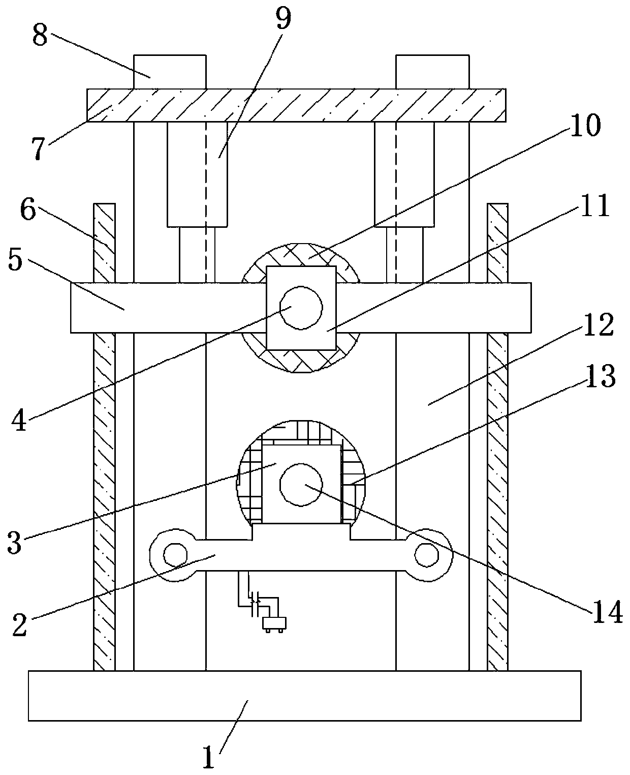
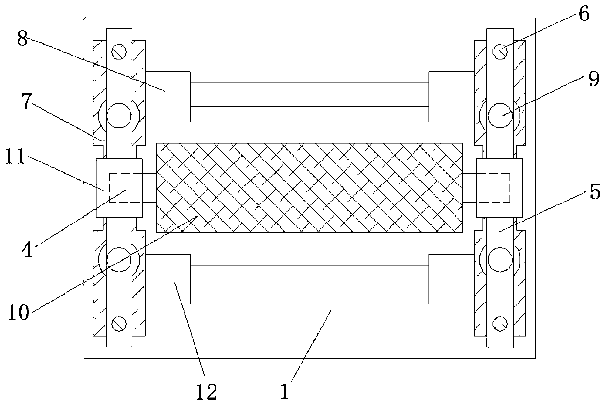
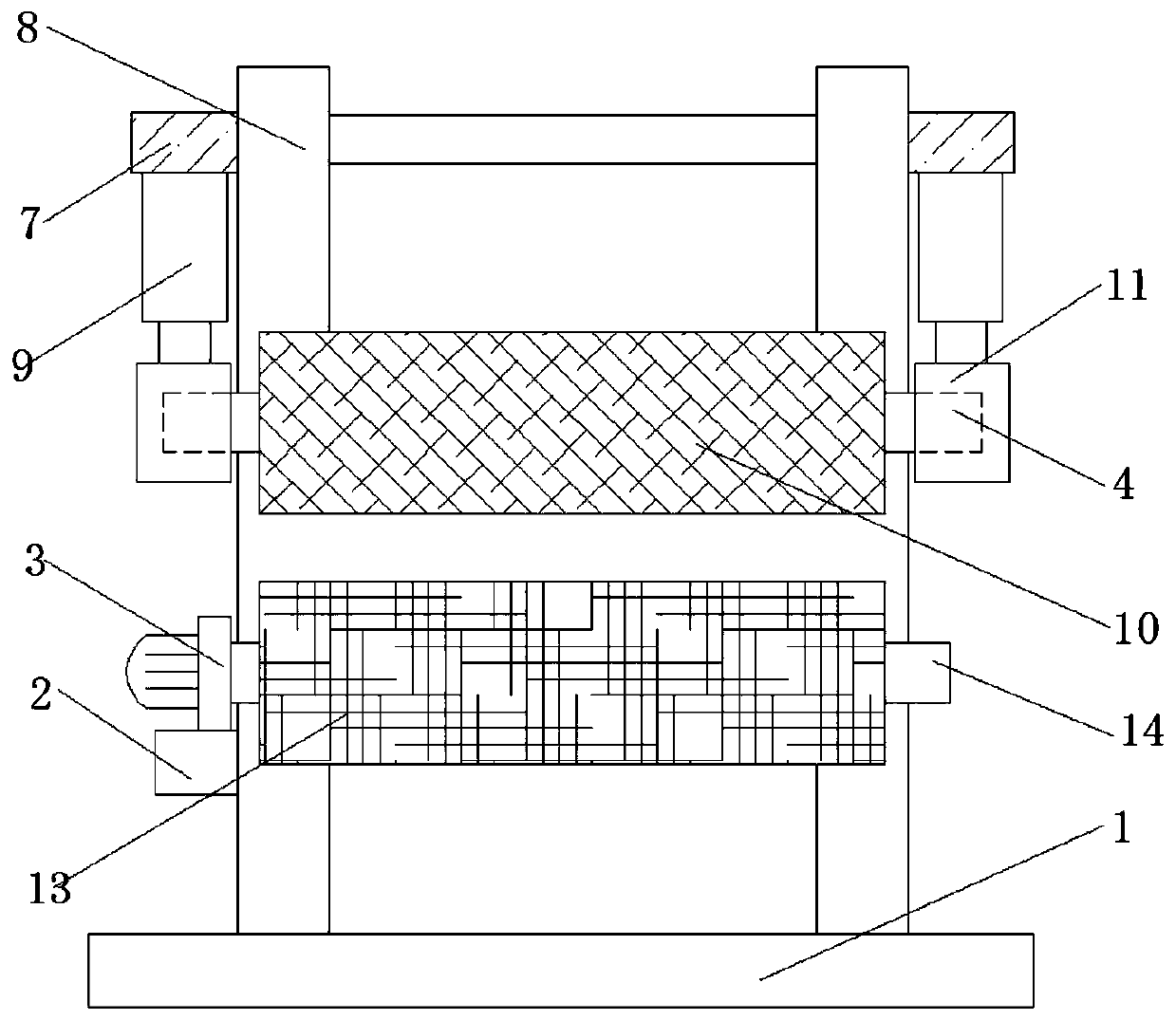
[0021] Example: refer to Figure 1-3 , a blanking machine for high-strength rebar, the middle blocks 11 are connected with upper rollers 10 through installation rods 4, the upper rollers 10 are connected with installation rods 4, and one end of the installation rods 4 is inserted into the middle block 11, the middle block 11 is arranged between the first vertical bar 8 and the second vertical bar 12 through the connecting plate 5, the opposite end of the upper side roll 10 is provided with the lower side roll 13, and the first vertical bar 8 is far away from the mounting plate 7 The side wall bolts are connected with a load-bearing plate 2, and one end of the load-bearing plate 2 is bolted to the second vertical bar 12, and the upper wall of the load-bearing plate 2 is screwed with a motor 3, and the output end of the motor 3 is connected to a rotating shaft through a coupling. The shaft 14 and the rotating shaft 14 are arranged on the lower side pressure roller, and one end w...


PUM


Abstract

The invention relates to a cogging mill of high-strength deformed steel bars, in particular to a cogging mill of PSB830 high-strength deformed steel bars. The problems that in cogging mills in the prior art, outer structures do auxiliary work, instability generated when the cogging mills carry out steel rolling processing on deformed steel bars and shift is increased, and safety generated when thecogging mills are utilized for processing the deformed steel bars is reduced are solved. The cogging mill comprises a base, a first vertical rod and a second vertical rod. Middle blocks are connectedand arranged between the first vertical rod and the second vertical rod. Connecting plates are fixed to the two end walls of each middle block through screws. Round through holes are formed in the upper walls of the connecting plates, and guide rods are arranged in the through holes in an inserted connection manner. One end of each guide rod is fixed to the base through a stud. An upper roller isconnected between the middle blocks through mounting rods. Through the arrangement of the cogging mill, a lower roller achieves the functions of guide and conveying on the rolled deformed steel bars,and the safety generated when the cogging mill is utilized for carrying out circulating steel rolling processing on the deformed steel bars is also improved.

Description

technical field [0001] The invention relates to a blanking machine for high-strength rebar, in particular to a blanking machine for PSB830 high-strength rebar. Background technique [0002] The blanking machine is suitable for rough rolling, and it is an ideal rolling mill equipment for rolling plain carbon steel, alloy steel, stainless steel, copper, aluminum, etc. Roll the rolled piece out of the heating furnace into the required shape, size, structure and performance, so that the lower stand rolling mill can bite. The blanking machine is used for rough machining and rolling of raw materials, so it needs a large capacity. Most of the rolling mills have been defined and classified. According to the different roll diameters, they can be divided into various specifications such as 700mm, 750mm, and 850mm. According to its different functions, it is generally divided into ACF billet blooming mill, ACP square slab blooming mill, AP billet rolling mill and other categories. ...

Claims


Application Information

Patent Timeline
Patent Type & Authority Applications(China)
IPC IPC(8): B21B1/16B21B13/02
Inventor 刘苏军赵志波赵飞飞
Owner JINGYE STEEL CO LTD
Why Eureka
Try Eureka