Automatic feeding mechanical hand mechanism for punching machine

A technology of automatic feeding and manipulators, applied in metal processing equipment, feeding devices, manufacturing tools, etc., can solve problems such as low work efficiency and damage to aluminum sheets

Inactive Publication Date: 2019-05-21
苏州冬宝光电科技有限公司
View PDF13 Cites 5 Cited by
  • Summary
  • Abstract
  • Description
  • Claims
  • Application Information

AI Technical Summary

Problems solved by technology

[0003] In view of this, the present invention provides an automatic feeding manipulator mechanism for punching machines, which aims to solve the problems of manual loading labor burden, low work efficiency, and easy damage to aluminum sheets in the prior art, and can replace Manually and automatically complete the feeding work, which not only protects the quality of aluminum sheets, but also reduces the labor burden of workers and improves work efficiency

Method used


Image

  • Automatic feeding mechanical hand mechanism for punching machine
  • Automatic feeding mechanical hand mechanism for punching machine
  • Automatic feeding mechanical hand mechanism for punching machine

Examples


Embodiment 1

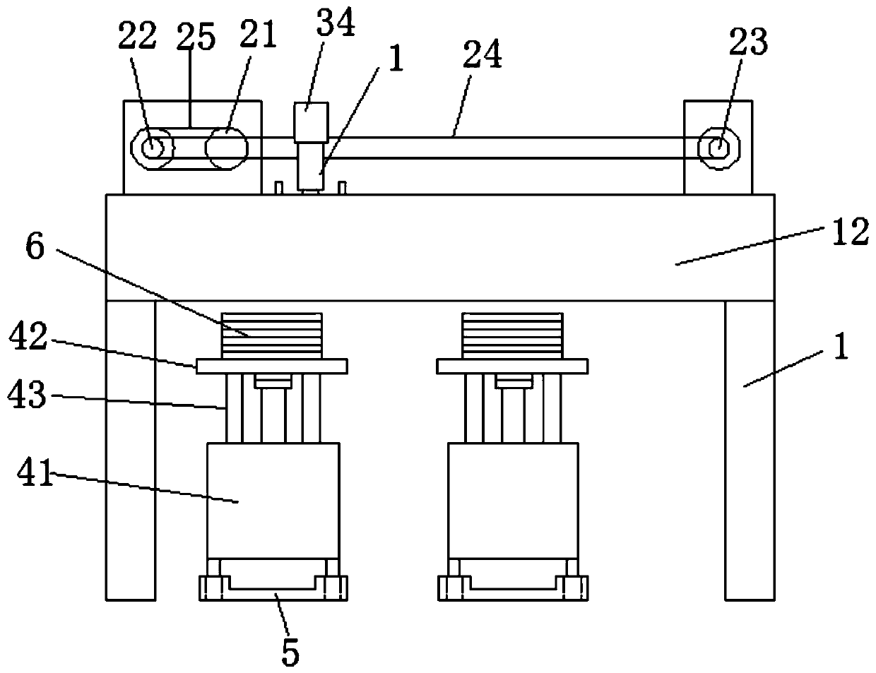
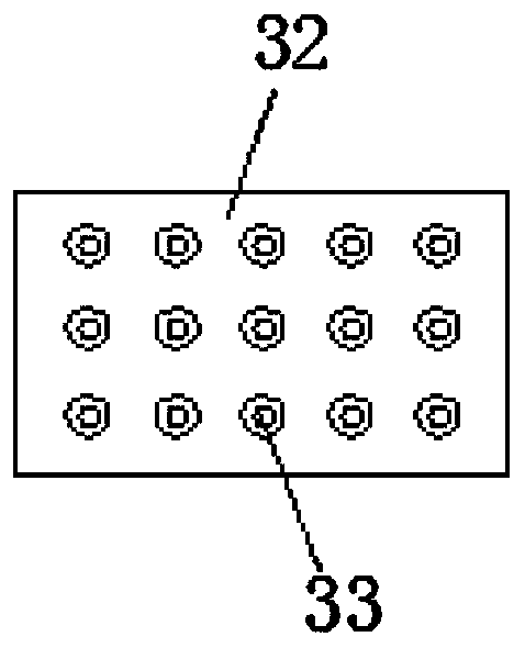
[0020] see Figure 1-4 , the figure shows an automatic feeding manipulator mechanism for a punching machine provided by Embodiment 1 of the present invention, which includes a feeding rack 1, a feeding table located below the feeding rack 1, and a mobile connection to the feeding rack 1. The feeding manipulator includes a linear translation assembly and an up and down lifting assembly. The linear translation assembly includes a drive motor, a drive wheel 21, a driving gear 22, a transmission gear 23, and a chain 24. The drive motor is connected to the drive wheel 21, and the drive wheel 21 passes through the Belt 25 transmission connects driving gear 22, and driving gear 22 connects driven gear 23 by chain 24 transmission; Suction cups 33 evenly distributed, the suction cups are connected to the vacuum generator through the air pipe;

[0021] An automatic feeding manipulator mechanism for a stamping machine provided in this embodiment, the setting of the feeding rack 1 provid...

Embodiment 2

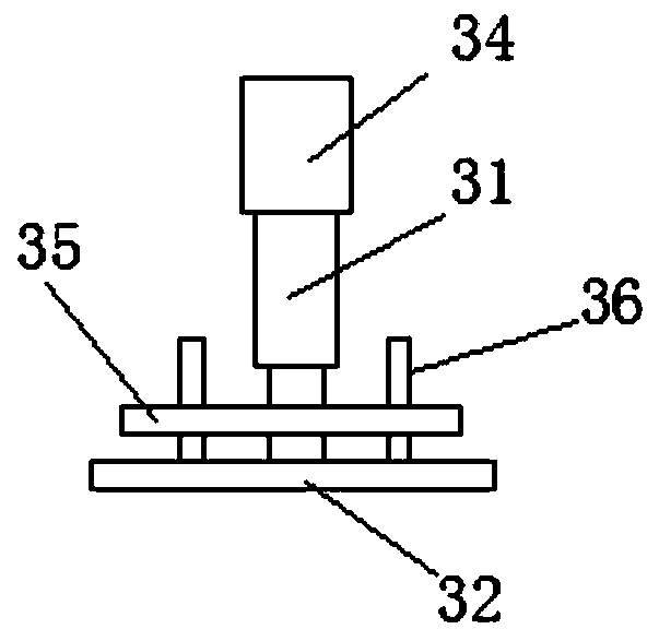
[0023] see Figure 4 , the figure shows an automatic feeding manipulator mechanism for punching machines provided by Embodiment 2 of the present invention. This embodiment further makes the following technical solutions as improvements on the basis of the above embodiments: For the moving direction of the linear translation assembly, a slide rail 11 is provided on the inside of the loading rack 1; a guide plate 35 is provided between the lifting cylinder 31 and the manipulator 32, and the guide plate 35 is slidably connected to the slide rail 11.

[0024] Through the above-mentioned further improvement, this embodiment has the following advantages compared with the prior art: when moving, the guide plate 35 moves along the slide rail 11, which not only has a guiding effect, but also is less likely to be cheap, and improves the feeding accuracy.

Embodiment 3

[0026] see figure 2 , the figure shows an automatic feeding manipulator mechanism for punching machines provided by Embodiment 3 of the present invention. On the basis of the above embodiments, this embodiment further makes the following technical solutions as improvements: guide plate A first guide post 36 for guiding is also arranged between 35 and the suction plate.

[0027] Through the above further improvements, this embodiment has the following advantages compared with the prior art: the setting of the first guide post 36 can improve the precision of the up and down movement of the manipulator 32 , thereby improving the feeding precision.


PUM


Abstract

The invention provides an automatic feeding mechanical hand mechanism for a punching machine. The automatic feeding mechanical hand mechanism comprises a feeding frame, feeding tables and a feeding mechanical hand movably connected with the feeding frame; the feeding mechanical hand comprises a linear translation assembly and a vertical lifting assembly; the linear translation assembly comprises adriving motor, a driving wheel, a driving gear, a transmission gear and a chain, the driving motor is in transmission connection with the driving wheel, the driving wheel is in transmission connection with the driving gear through a belt, and the driving gear is in transmission connection with a driven gear through a chain; the vertical lifting assembly comprises a lifting air cylinder and a mechanical hand connected with the lifting air cylinder, the mechanical hand is a suction plate, and the bottom of the suction plate is provided with a plurality of uniformly-distributed suction cups; andthe lifting air cylinder is connected with the chain through an installation seat, and the chain is arranged in the horizontal direction of the feeding frame. The automatic feeding mechanical hand mechanism for the punching machine can replace manpower to automatically complete feeding work, the quality of aluminum sheets is ensured, meanwhile, the labor burden of workers is lowered, and the working efficiency is improved.

Description

technical field [0001] The invention relates to an automatic feeding manipulator, in particular to an automatic feeding manipulator mechanism for a stamping machine. Background technique [0002] As the back shell part of the display, the display backplane plays an important role in protecting the display. When the display backplane is being processed, it is formed by stamping after cutting the aluminum strip. The aluminum sheets and strips are stored in rolls. After the strips are released during processing, cutting equipment is used to cut them sequentially, and then the cut aluminum sheets are manually sent to the stamping equipment for forming processing. With the continuous improvement of the automation level of the production line, manual feeding can no longer meet the needs of automated production, which not only increases the labor burden of labor, but also reduces work efficiency, and it is easy to cause damage to the aluminum sheet during the manual feeding proces...

Claims


Application Information

Patent Timeline
Patent Type & Authority Applications(China)
IPC IPC(8): B21D43/10
Inventor 陈刚
Owner 苏州冬宝光电科技有限公司
Why Eureka
Try Eureka