Foundry sand treatment mixing and rolling equipment
A sand treatment and foundry technology, applied in the field of sand treatment and mixing equipment in foundries, can solve the problems of unguaranteed sand quality, failure to remind, machine idling, etc., to achieve cost reduction, avoid idling, and reduce dust.
- Summary
- Abstract
- Description
- Claims
- Application Information
AI Technical Summary
Problems solved by technology
Method used
Image

Examples
Embodiment Construction
[0023] The following will clearly and completely describe the technical solutions in the embodiments of the present invention with reference to the accompanying drawings in the embodiments of the present invention. Obviously, the described embodiments are only some, not all, embodiments of the present invention.
[0024] Example.
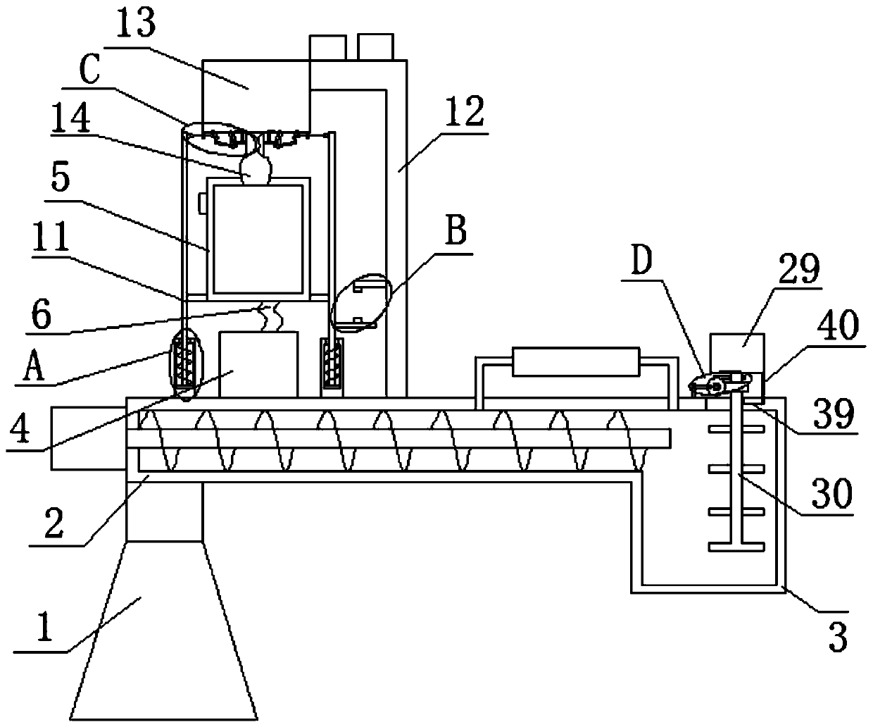
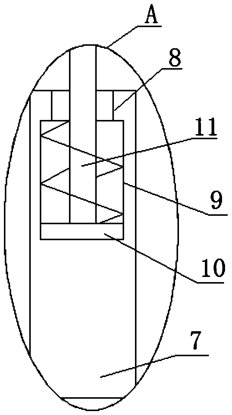
[0025] refer to Figure 1-5, a kind of equipment for sand processing and mixing in a foundry, comprising a machine base 1, a sand mixing pipe 2 is fixedly installed on the top side of the machine base 1, and a sand mixing box 3 is fixedly installed on one side of the sand mixing pipe 2, and the sand mixing box 3 is connected to the The sand mixing pipe 2 is connected, and the top side of the sand mixing pipe 2 is movably installed with an unloader 4, and both sides of the unloader 4 are provided with fixed columns 7 fixedly installed on the top side of the sand mixing pipe 2, and the two fixed The top of the column 7 is provided with a telescopic g...
PUM
 Abstract
Description
Claims
Application Information
PatSnap Eureka turns technology decisions into work you can execute. Powered by our Innovation Knowledge Graph, it runs expert workflows across engineering, life sciences, materials and intellectual property. Get your review-ready output in minutes.


