
A point laser line calibration method and system for robot assembly

A calibration method and robot technology, applied in the field of robot vision, can solve the problems of low accuracy and high cost of calibrating assembly components, and achieve the effects of improving accuracy, reducing calibration cost and high efficiency

Active Publication Date: 2021-03-30
武汉库柏特科技有限公司
View PDF6 Cites 1 Cited by
  • Summary
  • Abstract
  • Description
  • Claims
  • Application Information

AI Technical Summary

Problems solved by technology

[0005] The technical problem to be solved by the present invention is to provide a point laser line calibration method and system for robot assembly in view of the shortcomings of high cost and low accuracy of calibration assembly components in the robot assembly process in the prior art

Method used


Image

  • A point laser line calibration method and system for robot assembly
  • A point laser line calibration method and system for robot assembly
  • A point laser line calibration method and system for robot assembly

Examples


Embodiment 1

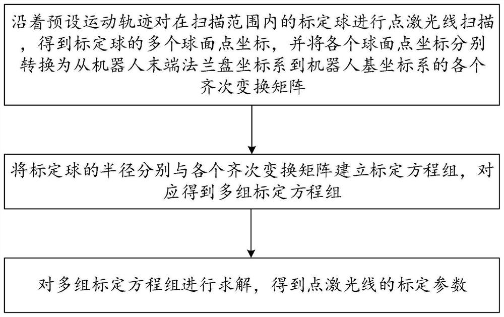
[0022] like figure 1 As shown, a schematic flow chart of a point laser line calibration method for robot assembly according to an embodiment of the present invention, the method includes:

[0023] Carry out point laser line scanning on the calibration ball within the scanning range along the preset motion trajectory to obtain multiple spherical point coordinates of the calibration ball, and convert the coordinates of each spherical point into the coordinate system from the end flange of the robot to the robot base. Individual homogeneous transformation matrices for the coordinate system.

[0024] The radius of the calibration sphere and each homogeneous transformation matrix are used to establish a calibration equation group, correspondingly to obtain multiple sets of calibration equations, and solve the multiple sets of calibration equations to obtain the calibration parameters of the point laser line.

[0025] Preferably, each calibration equation group includes a coordinat...

Embodiment 2

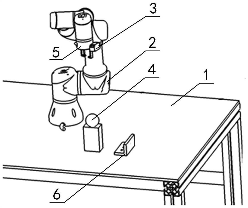
[0048] like figure 2 As shown, a schematic structural diagram of a point laser line marking system for robot assembly according to an embodiment of the present invention, figure 2 Among them, a robot 2 , a calibration ball 4 and an assembly 6 are fixed on the workbench 1 , the flange 5 at the end of the robot is equipped with a point laser sensor 3 , and the calibration ball 4 is set within the scanning range of the point laser sensor 3 .

[0049] The point laser sensor 3 is used to perform point laser line scanning on the calibration ball 4 within the scanning range according to the preset motion track when the robot 2 drives the point laser sensor 3 to move according to the preset motion track, so as to obtain multiple images of the calibration ball 4 Spherical point coordinates.

[0050] The robot 2 is used to convert the coordinates of each spherical point into homogeneous transformation matrices from the robot end flange coordinate system to the robot base coordinate s...


PUM


Abstract

The invention relates to a point laser ray calibration method and system used for robot assembling. The method comprises the steps that point laser ray scanning is performed on spherical displacers within the scanning scope along the preset moving trajectory, the multiple spherical point coordinates of the spherical displacers are obtained, and all the spherical point coordinates are converted into all homogeneous transformation matrixes from a robot tail end flange plate coordinate system to a robot base coordinate system; the radiuses of the spherical displacers and the homogeneous transformation matrixes are used for establishing calibration equation sets, and the multiple calibration equation sets are obtained correspondingly; and the multiple calibration equation sets are solved, andcalibration parameters of point laser rays are obtained. According to the point laser ray calibration method and system used for robot assembling, the accuracy degree of the calibration parameters isincreased, the calibration cost is lowered, and the method and system have the advantages of simple algorithm, high efficiency, high calibration precision and the like.

Description

technical field [0001] The invention relates to the technical field of robot vision, in particular to a point laser line calibration method and system for robot assembly. Background technique [0002] In order to ensure the alignment of the assembly in the robot assembly process, the robot vision technology has been widely used in the body robot assembly, the robot end assembly process sensor, the sensor can effectively ensure the accurate pose of the assembly in the robot. [0003] At present, the sensors are mainly force sensors and laser sensors. The force sensors collect force data and calculate the force data through the force control algorithm. The laser sensor collects the displacement data and calculates the displacement data through the displacement algorithm to calibrate the pose of the assembly on the robot. [0004] However, the cost of the force sensor is too high, and the pose of the laser sensor at the end of the robot is inaccurate, which will directly reduce...

Claims


Application Information

Patent Timeline
Patent Type & Authority Patents(China)
IPC IPC(8): B25B11/00B25J19/02
Inventor 李淼闫琳张少华付中涛郭盛威李勇岳珍刘小博
Owner 武汉库柏特科技有限公司
Learn More