Collection of secondary electrons through the objective lens of a scanning electron microscope

a scanning electron microscope and objective lens technology, applied in the field of scanning electron microscope, can solve the problems of small number of impacting electrons giving rise to auger electrons, not being able to efficiently collect, and not being able to achieve the effect of high-resolution lens performance, reducing signal acquisition time, and increasing secondary electron signal

Inactive Publication Date: 2005-09-20
FEI CO
View PDF17 Cites 29 Cited by
  • Summary
  • Abstract
  • Description
  • Claims
  • Application Information

AI Technical Summary

Benefits of technology

[0016]The present invention comprises a scanning electron microscope system that includes through-the-lens collection of secondary electrons, and is particularly suited for collecting Auger electrons. Because the electron collection system does not physically or electrically interfere with the primary beam optics, a high current, high resolution primary beam objective lens can be used, thereby significantly increasing the secondary electron signal and reducing signal acquisition time compared to prior art systems without significantly compromising the performance of the high resolution lens.

Problems solved by technology

Unfortunately, only a small number of the impacting electrons give rise to Auger electrons.
Since opening 7 collects electrons from only a small portion of the hemisphere above the sample, it is not an efficient collector, and side-mounted AES systems on SEMs are not very sensitive, that is, they are not able to detect extremely small concentrations of a material.
Moreover, such side-mounted electron collectors are incompatible with high resolution electron lenses for SEMs, because the magnetic field from the lenses greatly reduces the number of electrons collected.
The higher beam current can cause more sample damage than a scanning instrument would cause at comparable beam energies.
This is also an imaging type instrument as opposed to a scanning instrument and is very complex.
Such attempts have met with limited success.
A primary problem in incorporating through-the-lens collection of secondary electrons in an SEM is the difficulty of separating the secondary electrons returning through the lens along the same path as the primary beam electrons.
The separating or deflecting device used in the TEM Auger systems to separate the electrons transmitted back through the lens, while producing minimal aberrations in the high energy TEM beam, can cause severe aberrations in the lower energy SEM primary beam, thereby reducing the resolution and usefulness of the SEM.
Although the aberrations can be reduced by known methods, such as designing a primary beam crossover in the magnetic deflector or Wien filter device, such solutions restrict the optical flexibility of the primary beam optics, since such solutions tend to increase primary beam aberrations from another source, that is, beam interactions.
Moreover, such magnetic deflector devices have hysteresis, which can adversely affect performance.

Method used


Image

  • Collection of secondary electrons through the objective lens of a scanning electron microscope
  • Collection of secondary electrons through the objective lens of a scanning electron microscope
  • Collection of secondary electrons through the objective lens of a scanning electron microscope

Examples


Embodiment Construction

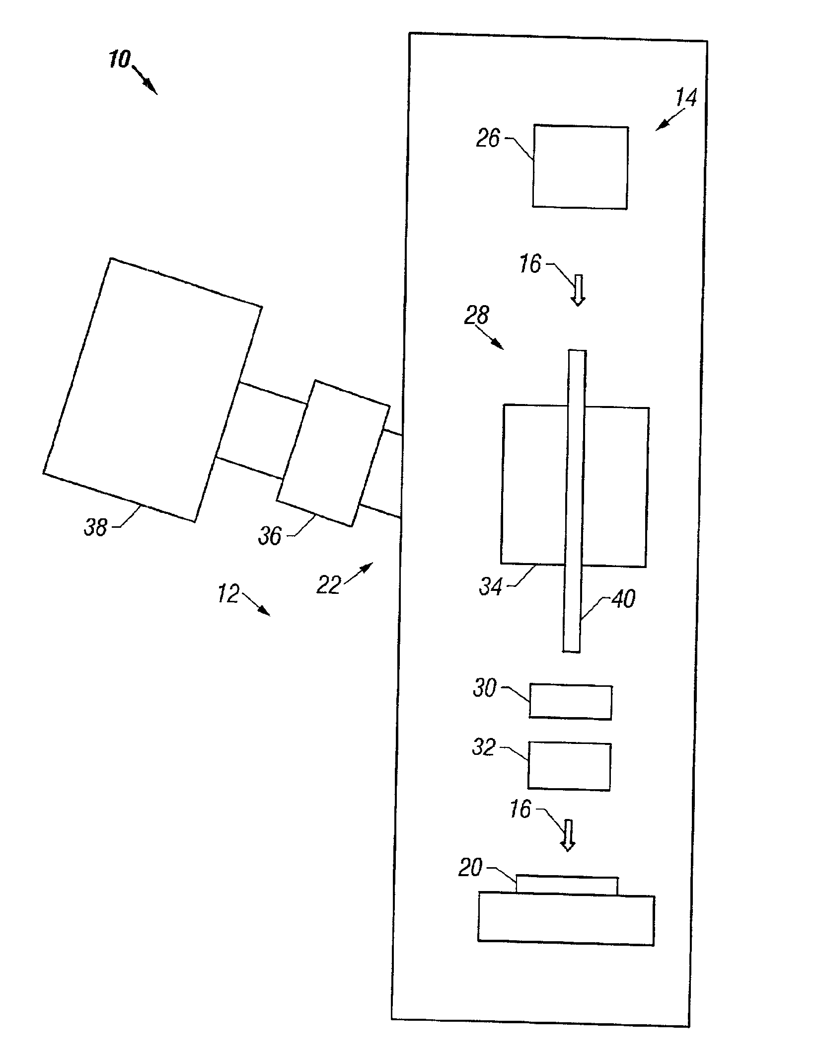
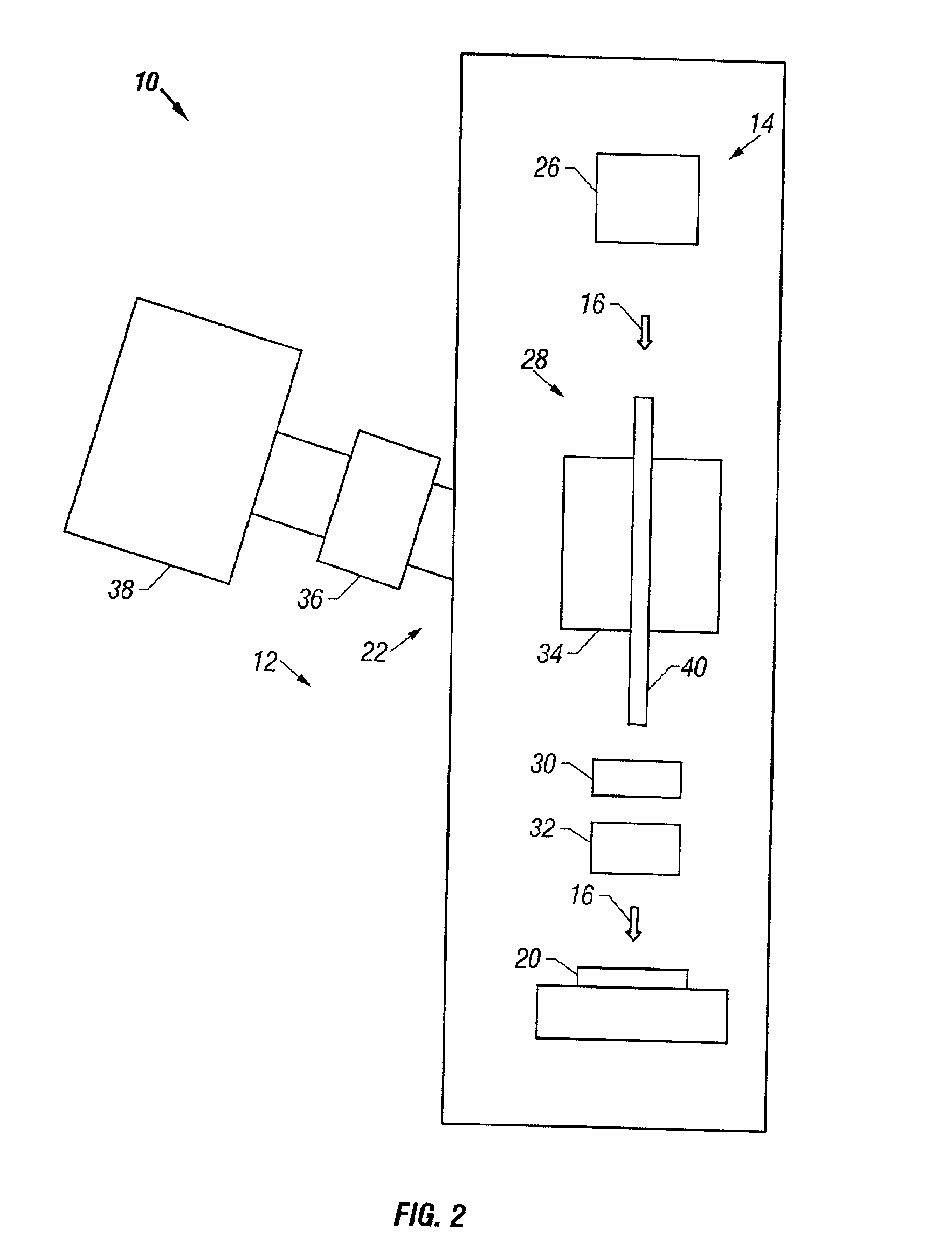
[0038]General features of preferred embodiments of scanning electron microscope systems having through-the-lens secondary electron detector systems according to the present invention are illustrated in the following description and figures.

[0039]The inventive system preferably uses a high resolution objective lens, such as an extended field (snorkel) lens, an immersion lens, or a dual pole magnetic lens. Secondary electrons are collected through the objective lens and then deflected away from the primary beam axis to a detector, preferably an Auger electron spectrometer. In a preferred embodiment, an electrostatic lens inside of the primary beam objective lens accelerates the Auger electrons away from the sample and reduces the angle of secondary electrons exiting the objective lens. A deflector, such as a spherical capacitor, deflects the Auger electrons out of the primary beam path. The primary beam is shielded as it passes through the deflector to prevent aberration of the primar...


PUM

PropertyMeasurementUnit
beam energyaaaaaaaaaa
energyaaaaaaaaaa

Abstract

A high resolution scanning electron microscope collects secondary Auger electrons through its objective lens to sensitively determine the chemical make-up with extremely fine positional resolution. The system uses a magnetic high resolution objective lens, such as a snorkel lens or a dual pole magnetic lens which provides an outstanding primary electron beam performance. The Auger electrons are deflected from the path of the primary beam by a transfer spherical capacitor. The primary beam is shielded, by a tube or plates, as it traverses the spherical capacitor to prevent aberration of the primary beam and the external wall of the shield maintains a potential gradient related to that of the spherical capacitor to reduce aberration of the primary electron beam. The coaxial configuration of the primary electron beam and the collected secondary electron beam allows the Auger image to coincide with the SEM view.

Description

[0001]This application claims priority from U.S. Prov. App. No. 60 / 199,280, filed Apr. 24, 2000.TECHNICAL FIELD OF THE INVENTION[0002]The present invention relates to determining the properties of microscopic structures and, in particular, to a scanning electron microscope that collects through its objective lens secondary electrons for analysis, such as Auger electron spectroscopy.BACKGROUND OF THE INVENTION[0003]Electronic devices are constantly being made smaller to decrease their production costs and increase their operating speeds. To develop suitable new manufacturing processes and to correct defects in existing processes, engineers and scientists need analytical instruments that can create images of extremely small features and determine the chemical make-up of those features. Scanning electrons microscopes (SEMs) are widely used for imaging microscopic features, and Auger Electron Spectroscopy (AES) is often used to determine the chemical make-up of feature surfaces. AES can...

Claims


Application Information

Patent Timeline
Patent Type & Authority Patents(United States)
IPC IPC(8): H01J37/244H01J37/28H01J37/252G01Q10/04G01Q30/02G01Q30/04H01J37/141
CPCH01J37/141H01J37/244H01J37/28H01J2237/24485
Inventor GERLACH, ROBERT L.VAN DER MAST, KAREL D.SCHEINFEIN, MICHAEL R.
Owner FEI CO
Why Eureka
Try Eureka