Continuous speed-changing shunt type hybrid power assembly

A technology of hybrid power and hybrid power modules, which is applied in the direction of hybrid vehicles, power devices, air pressure power devices, etc., can solve the problems of high fuel consumption and poor shifting quality, and achieve low fuel consumption, high shifting quality, The effect of saving resources

Active Publication Date: 2019-05-21
GEELY AUTOMOBILE INST NINGBO CO LTD +1
View PDF7 Cites 5 Cited by
  • Summary
  • Abstract
  • Description
  • Claims
  • Application Information

AI Technical Summary

Problems solved by technology

[0005] The technical problem to be solved by the present invention is that the engine in the hybrid drive system of the automobile in the prior art often cannot work in the low fuel consumption area, the problem of high fuel consumption, and the hybrid drive system of the automobile still needs the clutch to shift gears in stages. The problem of poor quality

Method used


Image

  • Continuous speed-changing shunt type hybrid power assembly
  • Continuous speed-changing shunt type hybrid power assembly
  • Continuous speed-changing shunt type hybrid power assembly

Examples


Embodiment 1

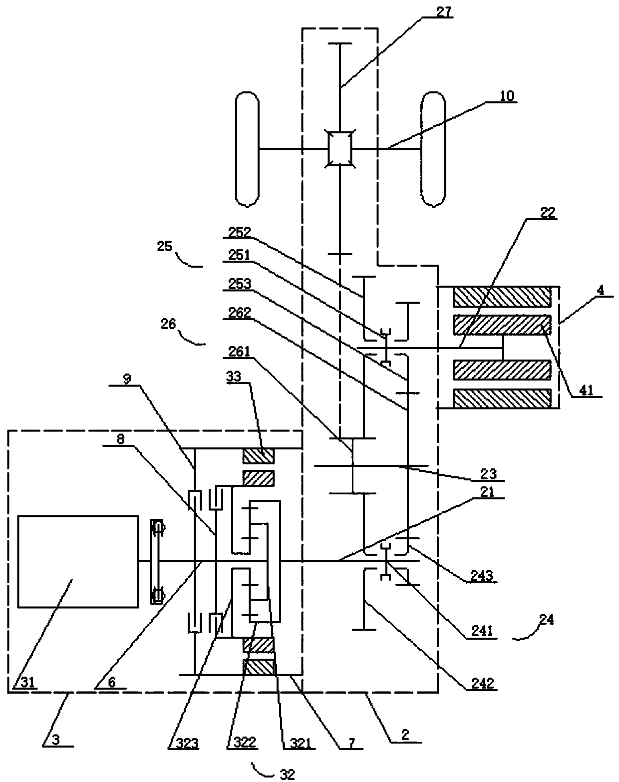
[0033] This embodiment provides a structure of a continuously variable split-flow hybrid powertrain, see figure 1 , the continuously variable split-flow hybrid powertrain includes a hybrid module 3, an electric module 4 and a gear shift module 2;

[0034] The gear shifting module 2 includes a first input shaft 21, a second input shaft 22, a first gear shifting mechanism 24, a second gear shifting gear 25 and an output shaft 23, and one end of the first input shaft 21 is connected to The power output end of the hybrid module 3 is connected, the other end of the first input shaft 21 is connected to the output shaft 23 through the first shift mechanism 24, and one end of the second input shaft 22 is connected to the The power output end of the electric module 4 is connected, and the other end of the second input shaft 22 is connected to the output shaft 23 through the second gear shift mechanism 25;

[0035] Wherein, both the first shifting transmission mechanism 24 and the seco...

Embodiment 2

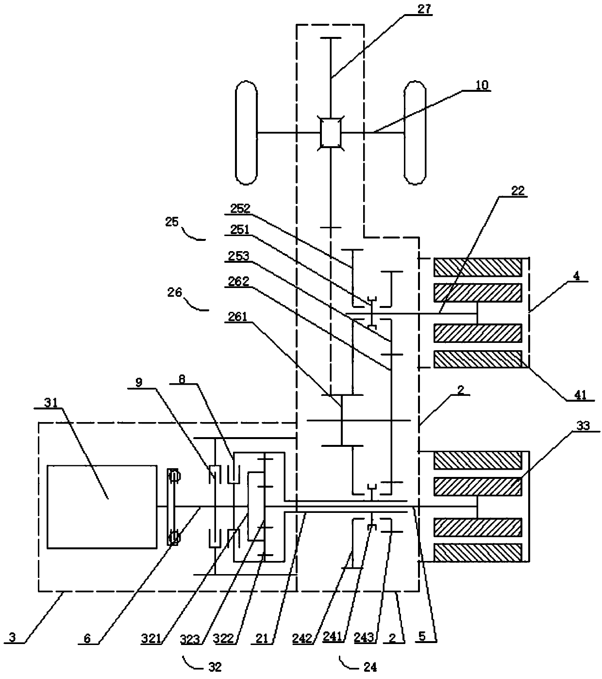
[0073] In this example, see figure 2 The difference from the first embodiment is that the first motor 33 is connected to the hybrid module 3 through the first transmission shaft 5 instead of the first motor 33 directly connected to the hybrid module 3 in the first embodiment. And after adding the first transmission shaft 5, the first input shaft 21 is set in a cylindrical shape, the first input shaft 21 is sleeved outside the first transmission shaft 5, and the connection relationship between other parts There is no change, and the function realized by this structure is the same as that realized in the first embodiment.

Embodiment 3

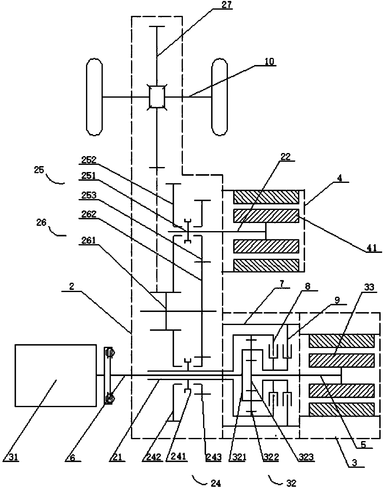
[0075] In this example, see image 3 , different from the second embodiment, in this embodiment only the positions of the shift transmission module 2 and the hybrid module 3 are exchanged, that is, the first input shaft 21 is sleeved on the second The connection relationship between other parts outside the transmission shaft 6 has not changed, and the function realized by this structure is the same as that realized in the second embodiment.


PUM


Abstract

The invention relates to the technical field of electric vehicle hybrid power and discloses a continuous speed-changing shunt type hybrid power assembly. The assembly comprises a hybrid power module,an electric module and a shifting speed-changing module, wherein the shifting speed-changing module comprises a first input shaft, a second input shaft, a first shifting speed-changing mechanism, a second shifting speed-changing mechanism and an output shaft; one end of the first input shaft is connected to a power output end of the hybrid power module, the other end of the first input shaft is connected to the output shaft through the first shifting speed-changing mechanism, one end of the second input shaft is connected to a power output end of the electric module, and the other end of the second input shaft is connected to the output shaft through the second shifting speed-changing mechanism. The assembly can achieve the functions of pure electric driving, mixed driving, energy brake recovery, stepless speed changing and the like so that an engine and a motor can work in areas with high efficiency, and electric energy is saved; moreover, gearshifts shit gears alternatively and change the speed continuously, so that the shifting quality is effectively improved.

Description

technical field [0001] The invention relates to the technical field of electric vehicle hybrid power, and discloses a continuously variable speed split flow hybrid power assembly. Background technique [0002] With the widespread application of electric vehicles, various vehicle drive systems have emerged, especially some hybrid power systems. The driving demand causes the motor to often work in the low-efficiency area, and the motor will cause a large loss if it can work in the low-efficiency area. In addition, the power of the motor cannot be fully utilized, and it often needs to work with over-rated torque, resulting in high heat generation. At the same time, some hybrids still retain the dual-clutch automatic transmission function and structure, and still use clutches to switch gears. Such hybrids have complex structures, poor shifting quality, and difficult control. [0003] The existing dual-motor four-speed or multi-speed double transmission mechanism often uses a pl...

Claims


Application Information

Patent Timeline
Patent Type & Authority Applications(China)
IPC IPC(8): B60K6/365B60K6/44B60K6/547
CPCY02T10/62Y02T10/92
Inventor 梁健
Owner GEELY AUTOMOBILE INST NINGBO CO LTD
Why Eureka
Try Eureka