Automated sock turn-over and end sewing device capable of moving downwards-turned stocking cylinder in multiple directions and application method

A multi-directional, sewing head technology, applied in the field of textile machinery, can solve the problems of reduced work efficiency, machine wear and loss, etc., and achieve the effect of convenient and stable operation, high degree of automation, and reduced failure rate

Pending Publication Date: 2019-05-21
赵镭
View PDF0 Cites 6 Cited by
  • Summary
  • Abstract
  • Description
  • Claims
  • Application Information

AI Technical Summary

Problems solved by technology

[0002] During the forming process of socks, the knitted socks need to be collected. The socks knitted by the sock knitting machine are usually facing outwards. Therefore, when sewing socks, a turner is needed to turn the socks inside out. After the sewing operation, the operation of the existing hosiery machine is relatively cumbersome, and the hosiery knitting process cannot be completed

Method used


Image

  • Automated sock turn-over and end sewing device capable of moving downwards-turned stocking cylinder in multiple directions and application method
  • Automated sock turn-over and end sewing device capable of moving downwards-turned stocking cylinder in multiple directions and application method
  • Automated sock turn-over and end sewing device capable of moving downwards-turned stocking cylinder in multiple directions and application method

Examples


Embodiment Construction

[0027] In order to deepen the understanding of the present invention, the invention will be further described in detail below in conjunction with the examples and accompanying drawings. The examples are only used to explain the present invention and do not constitute a limitation to the protection scope of the present invention.

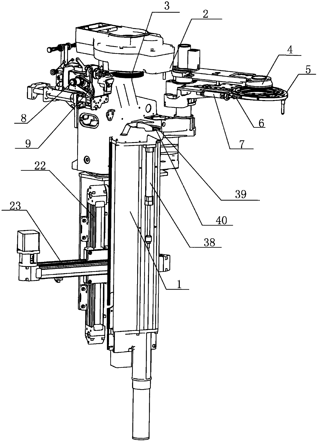
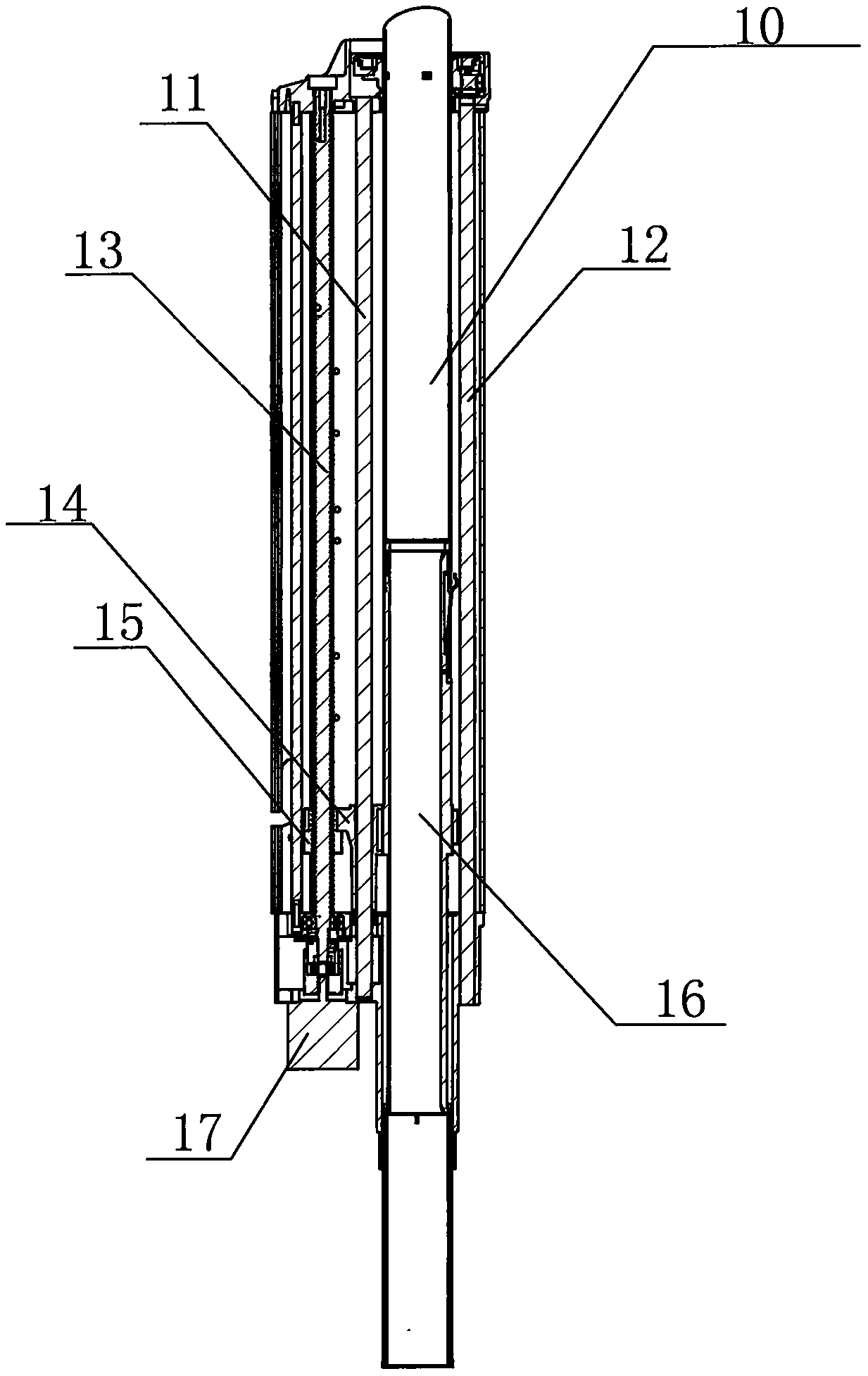
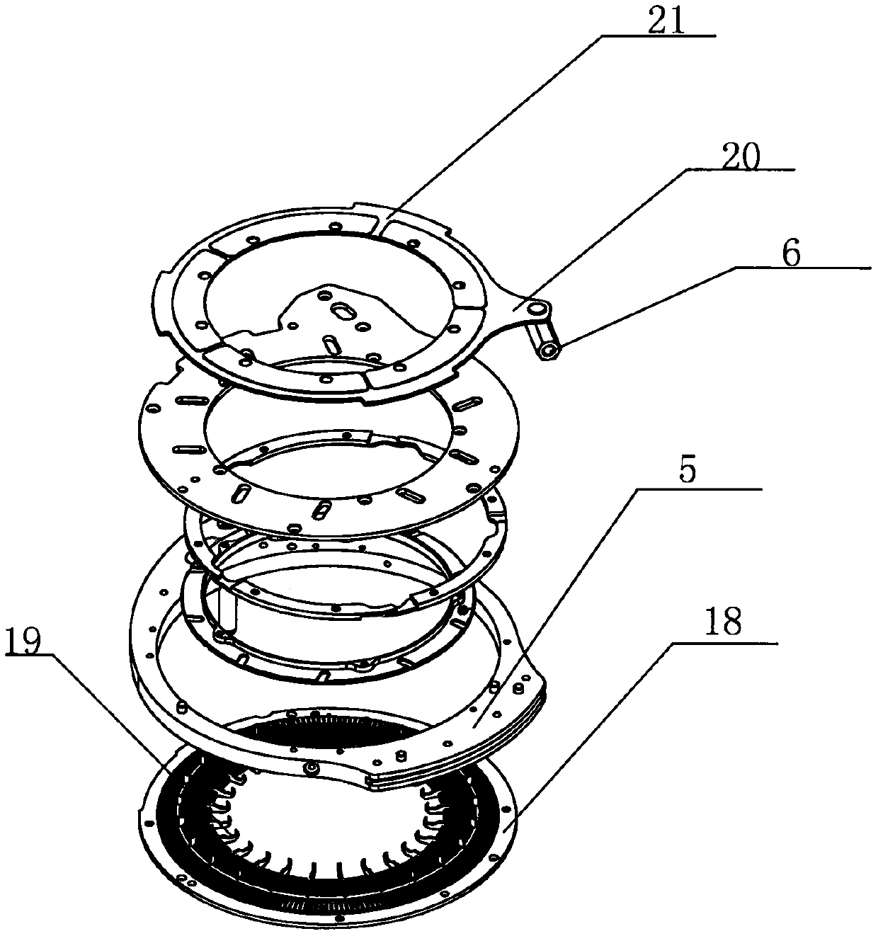
[0028] like Figures 1 to 6 Shown is an automatic sock-turning seam device with multi-directional movement of the bottom-turning sock tube, including a sock-knitting device, a sock-turning device, a seam head device and a seam plate 3, and the sock-knitting device and the seam plate 3 are installed There is a mechanical swing arm, and the mechanical swing arm grabs one end of the sock tube on the sock knitting device located below it, and swings it horizontally to the 3 sewing discs above the mechanical swing arm. The sock tube 1 is moved to the other end of the sock tube through the driving mechanism. There is a suction port on the top of the down-t...


PUM


Abstract

The invention discloses an automated sock turn-over and end sewing device capable of moving a downwards-turned stocking cylinder in multiple directions. The device comprises a sock knitting device, asock turn-over device, an end sewing device and a sewing disc. A mechanical swing arm is arranged between the sock knitting device and the sewing disc, grabs one end of a stocking leg on the sock knitting device below the mechanical swing arm and horizontally swings the stocking leg to the sewing disc above the mechanical swing arm, the sock turn-over device comprises the downwards-turned stockingcylinder, the downwards-turned stocking cylinder is moved to the other end of the stocking leg through a driving mechanism, and an air suction port is formed in the top of the downwards-turned stocking cylinder; the air suction port conducts suction through a suction device, makes the stocking leg fall in the downwards-turned stocking and then makes the downwards-turned stocking cylinder move tothe position below the sewing disc through the driving mechanism, the downwards-turned stocking cylinder and the sewing disc are located on the same straight line, the stocking leg on the sewing discis subjected to end sewing through the end sewing device, the driving mechanism comprises a horizontal guide rail and a vertical guide rail, the downwards-turned stocking cylinder is moved in multipledirections, and all work of sock turn-over and end sewing of the device is high in automation degree.

Description

technical field [0001] The invention relates to the field of textile machinery, in particular to an automatic sock turning device and a method for using it, which can move the bottom turning sock tube in multiple directions. Background technique [0002] During the forming process of socks, it is necessary to collect the knitted socks. The socks knitted by the sock knitting machine are usually facing outwards. Therefore, when sewing socks, a turner is needed to turn the socks inside out. After the sewing operation, the operation of the existing hosiery machine is relatively cumbersome, and the hosiery knitting process cannot be completed automatically, and the machine is severely worn and worn out, and the existing hosiery collection device cannot collect the hosiery well. Especially when the socks are too long, half of the sock tube remains on the sock knitting device, and the sock collecting device cannot move up, down, left, and right to a suitable position, which greatly...

Claims


Application Information

Patent Timeline
IPC IPC(8): D04B37/02D05B7/00D06G3/02D04B9/40
Inventor 赵镭
Owner 赵镭
Why Eureka
Try Eureka