
High-precision low-flow detection device based on constant power

A technology of constant power and detection device, applied in measurement device, liquid/fluid solid measurement, volume change compensation/correction device, etc., can solve the problems of large dispersion, formation water pollution, and inability to meet the production needs of low permeability wells, etc. To achieve the effect of convenient processing and molding, easy maintenance and replacement, excellent thermal conductivity and corrosion resistance

Active Publication Date: 2019-05-21
BC P INC CHINA NAT PETROLEUM CORP +1
View PDF8 Cites 3 Cited by
  • Summary
  • Abstract
  • Description
  • Claims
  • Application Information

AI Technical Summary

Problems solved by technology

[0002] In the process of oil field production, in order to detect the changing parameters in the development well in time, it is necessary to carry out production logging after casing. Well instruments include tracer flowmeters, turbine flowmeters, ultrasonic flowmeters, and electromagnetic flowmeters. Tracer flowmeters are chemical source radioactive instruments that pollute formation water; turbine flowmeters, ultrasonic flowmeters, and electromagnetic flowmeters Dispersion is large, the start-up displacement is higher than 5 cubic meters per day, and 80% of the development wells in most oil fields are low-permeability wells, and the flow rate is lower than 3 cubic meters per day. Therefore, the above-mentioned existing flow detection instruments cannot meet the requirements of low-permeability well production needs

Method used


Image

  • High-precision low-flow detection device based on constant power
  • High-precision low-flow detection device based on constant power
  • High-precision low-flow detection device based on constant power

Examples


Embodiment Construction

[0042] The present invention is described in further detail below in conjunction with accompanying drawing:

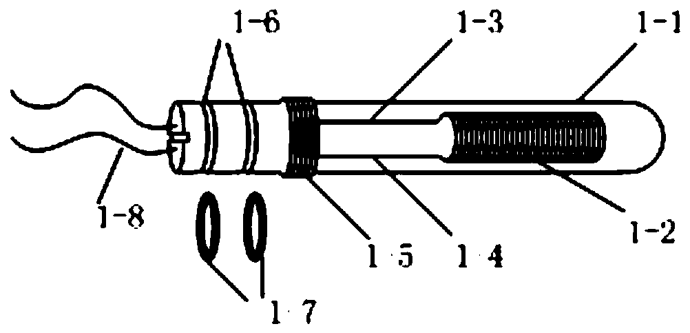
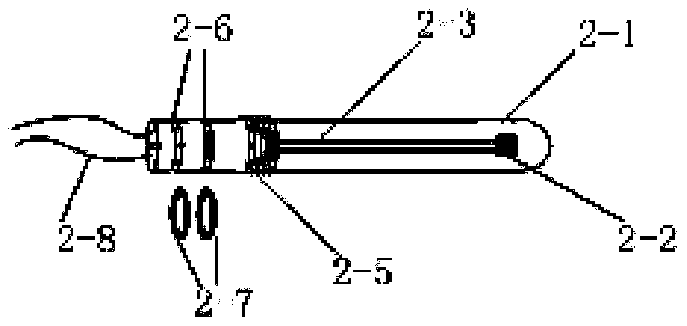
[0043] Such as Figure 1-8 , the high-precision low-flow detection device based on constant power disclosed by the present invention includes a constant power heating element 1, a temperature sensing element 2, an integrated functional module, a circuit mounting shell 5, and a flow sensor mounting shell 6; the constant power heating element 1 and the temperature sensing body 2 are installed on the flow sensor installation housing 6, one end of the flow sensor installation housing 6 is sealed, and the other end is connected to the integrated function module, and the integrated function module is installed inside the circuit installation housing 5 of one end of the hollow cylinder structure , the other end of the circuit installation shell 5 is sealed;

[0044]The flow sensor installation housing 6 is a cylindrical structure with a hollow section in the middle. The two ...


PUM


Abstract

The invention discloses a high-precision low-flow detection device based on constant power and belongs to the technical field of petroleum logging instruments. The device comprises a constant-power sensor and a detection processing transmission circuit connected with the constant-power sensor, wherein the detection processing transmission circuit is installed in a circuit installation shell, the constant-power sensor is installed in a flow sensor installation shell, the circuit installation shell and the flow sensor installation shell are connected in a screw-thread fit mode, and the free endof the circuit installation shell and the free end of the flow sensor installation shell are both sealed to form a pressure-bearing sealed column structure; and the constant-power sensor is composed of a constant-power heater and a temperature sensor, wherein the constant-power heater and the temperature sensor are oppositely installed at the two ends inside the flow sensor installation shell, anda gap is reserved between the end of the constant-power heater and the end of the temperature sensor. The device overcomes the limitation on starting discharge capacity of a traditional flow logginginstrument, a mechanical rotation device does not need to be arranged, the defect of a logging instrument in a domestic low liquid-producing well is overcome, and the device has the advantages of highsensitivity, high precision, simple structure and high stability.

Description

technical field [0001] The invention belongs to the technical field of petroleum logging instruments, and in particular relates to a high-precision low-flow detection device based on constant power. Background technique [0002] In the process of oil field production, in order to detect the changing parameters in the development well in time, it is necessary to carry out production logging after casing. Well instruments include tracer flowmeters, turbine flowmeters, ultrasonic flowmeters, and electromagnetic flowmeters. Tracer flowmeters are chemical source radioactive instruments that pollute formation water; turbine flowmeters, ultrasonic flowmeters, and electromagnetic flowmeters Dispersion is large, the start-up displacement is higher than 5 cubic meters per day, and 80% of the development wells in most oil fields are low-permeability wells, and the flow rate is lower than 3 cubic meters per day. Therefore, the above-mentioned existing flow detection instruments cannot m...

Claims


Application Information

Patent Timeline
IPC IPC(8): G01F15/02G01F15/14
Inventor 刘国权陈强董继辉任丽娟刘建成秦民君郭锋段银鹿张学李阳刘旭辉杨旭辉魏勇王易安
Owner BC P INC CHINA NAT PETROLEUM CORP
Learn More