Large field-of-view optical system detecting device and detecting method

An optical system and detection device technology, applied in the direction of testing optical performance, etc., can solve problems such as limited detection range, and achieve the effects of simple structure, high detection accuracy and simple operation

Pending Publication Date: 2019-05-21
西安科佳光电科技有限公司
View PDF0 Cites 5 Cited by
  • Summary
  • Abstract
  • Description
  • Claims
  • Application Information

AI Technical Summary

Problems solved by technology

[0005] The purpose of the present invention is to solve the shortcomings that the existing detection device can only detect the imaging quality of the central field of view of the optical system, and the d

Method used


Image

  • Large field-of-view optical system detecting device and detecting method
  • Large field-of-view optical system detecting device and detecting method
  • Large field-of-view optical system detecting device and detecting method

Examples


Embodiment Construction

[0050] Below in conjunction with accompanying drawing and specific embodiment content of the present invention is described in further detail:

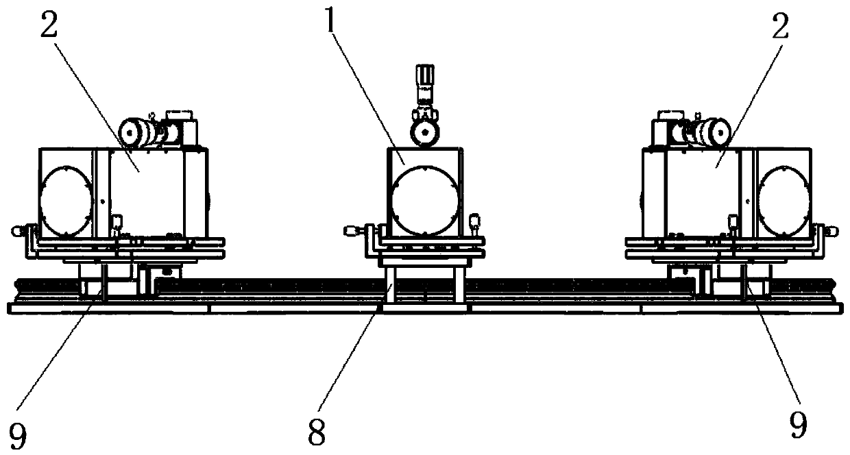
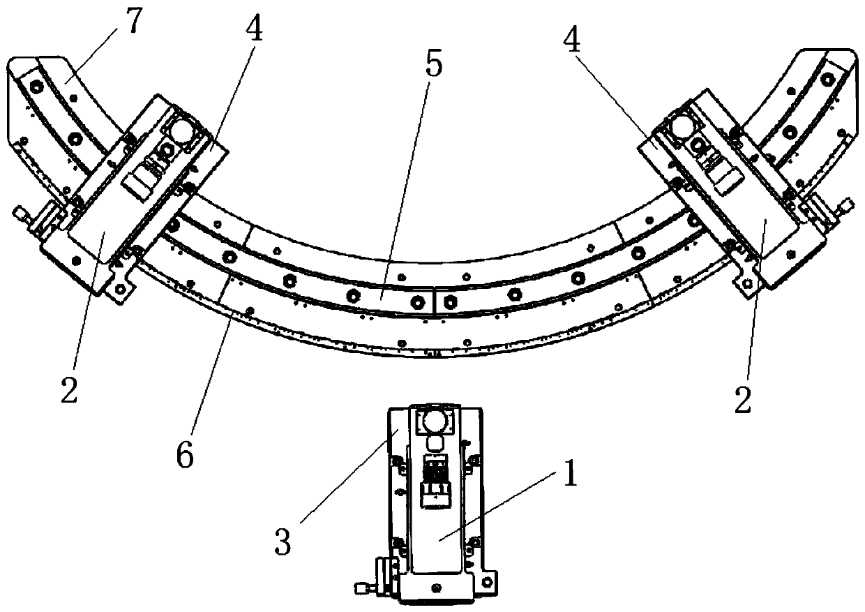
[0051] Such as Figure 1-Figure 7 As shown, a large field of view optical system detection device includes a circular arc guide rail 5 , a self-collimating collimator 1 and two collimator 2 .

[0052] Wherein, the arc guide rail 5 is fixed on the guide rail fixing base 7 by screws, its radius is 1000mm, and the central angle is 120°.

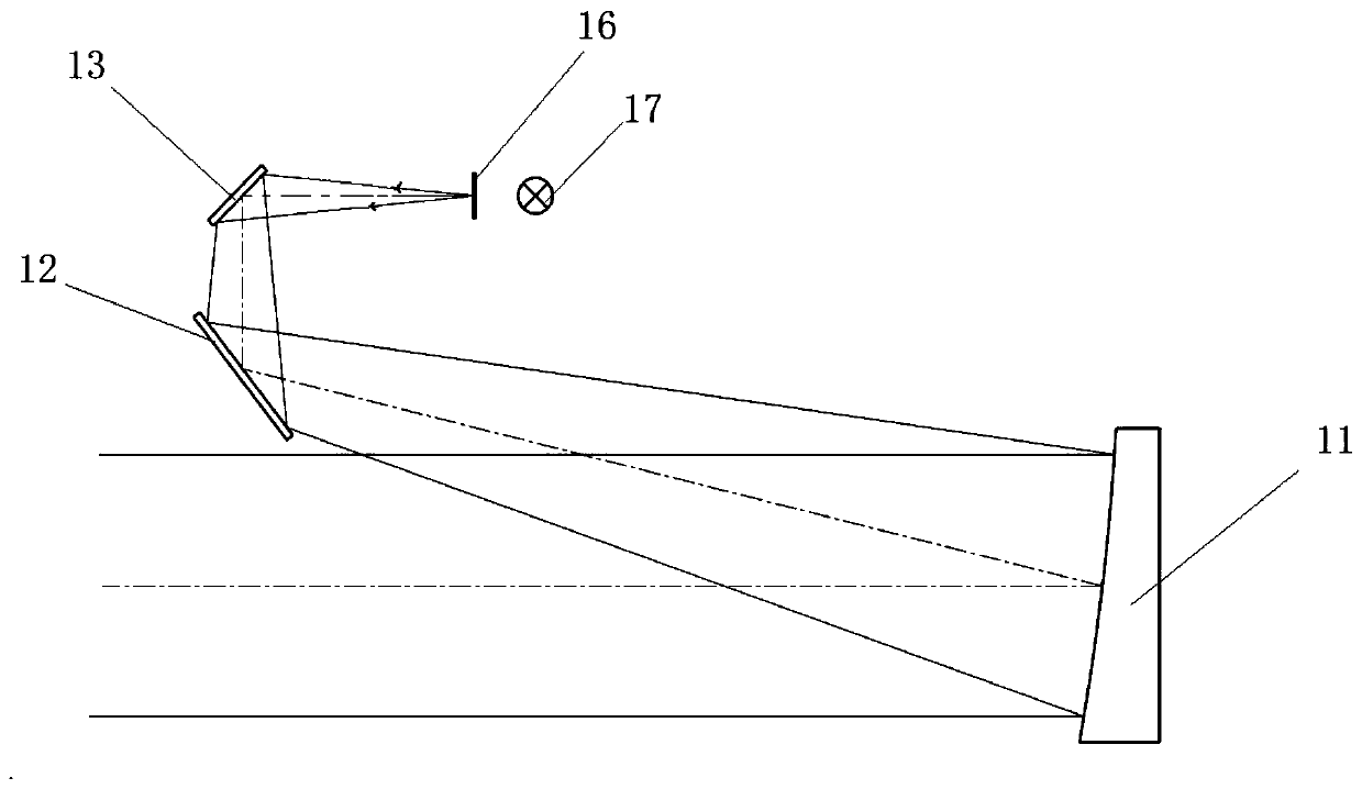
[0053] The self-collimation collimator 1 includes the self-collimation switching assembly 14 and the collimator 2, which can realize the switching between the self-collimation function and the detection function of the collimator 2, and when using different functions in the light path of the collimator 2 The same position is switched by mechanical positioning, and the self-collimation function is realized by adding a standard reflector 15 at the light outlet of the collimator 2 . The self-collimating ...


PUM


Abstract

The invention provides a large field-of-view optical system detecting device and detecting method, thereby solving problems that the existing detecting device can only detect the imaging quality of the central field of view of the optical system and thus the detection range is limited and the accuracy is low. The detecting device comprises a circular arc guide rail, a self-collimating collimator and at least one collimator. The self-collimating collimator is disposed outside the circular arc guide rail; and a first two-dimensional adjustment platform is disposed at the bottom of the self-collimating collimator. The at least one collimator is arranged on the circular arc guide rail in a sliding manner by a second two-dimensional adjustment platform; and the range of the field of view can beadjusted based on needs to carry out detection of the large field of view. The optical axes of parallel beams emitted by the self-collimating collimator and the at least one collimator are located onthe same horizontal plane and are intersected at the circle center of the circular arc guide rail. Therefore, the detection of the imaging quality of the large field of view of the optical system isrealized; and the operation becomes simple and the detection precision is high.

Description

technical field [0001] The invention belongs to the optical system detection technology, and relates to a large-field optical system detection device and a detection method. Background technique [0002] With the increasing application of optical systems, the demand for optical system performance testing and evaluation is also increasing, especially for infrared optical systems. The field of view of the optical system will affect the operating distance and accuracy of the system. The large field of view optical system can obtain more information and improve the efficiency of use, which is one of the current development directions of the optical system; and with the development of the current infrared focal plane technology , both linear array and area array infrared focal plane devices are becoming larger and larger, so there is an urgent need for infrared optical systems with large fields of view to match them. [0003] Due to some special application environments, the ima...

Claims


Application Information

Patent Timeline
IPC IPC(8): G01M11/02
Inventor 安飞马丽娜杨芝艳张亚平张建
Owner 西安科佳光电科技有限公司
Why Eureka
Try Eureka