Polarization conversion device

A polarization conversion and polarized light conversion technology, applied in the optical field, can solve the problems of low utilization rate of light energy and loss of light energy, and achieve the effect of improving the utilization rate of light energy

Inactive Publication Date: 2019-05-21
CHONGQING IQIYI INTELLIGENT TECHNOLOGY CO LTD
3 Cites 0 Cited by

AI-Extracted Technical Summary

Problems solved by technology

If the non-linearly polarized light-emitting screen is applied to the optical system of the principle of polarized display, it is common practice to add a polarizing filter in...

Method used

According to the scheme of the present invention, by the deflection conversion device that is made of multiple polarizers and 1/2 retarder, incident light is converted into polarized light, thereby can change non-polarized luminous screen into polarized light luminous screen, Moreover, the theoretical light ener...

Abstract

The invention aims to provide a polarization conversion device. The polarization conversion device comprises a plurality of sub-modules, wherein each sub-module comprises two polarizing devices and a1/2 delay sheet. The polarizing device is used for transmitting the first polarized light and reflecting the second polarized light. The 1/2 delay sheet is used for converting the first polarized light transmitted by the polarizer into second polarized light. The device has the advantages that by means of the deflection conversion device composed of the multiple polarizing devices and the 1/2 delay sheet, incident light is converted into polarized light, so that the non-polarized light emitting screen can be changed into a polarized light emitting screen, the theoretical light energy utilization rate of an optical system can be increased to 100%, and the light energy utilization rate is greatly increased.

Application Domain

Technology Topic

Image

  • Polarization conversion device
  • Polarization conversion device

Examples

  • Experimental program(1)

Example Embodiment

[0013] The present invention will be described in further detail below in conjunction with the accompanying drawings.
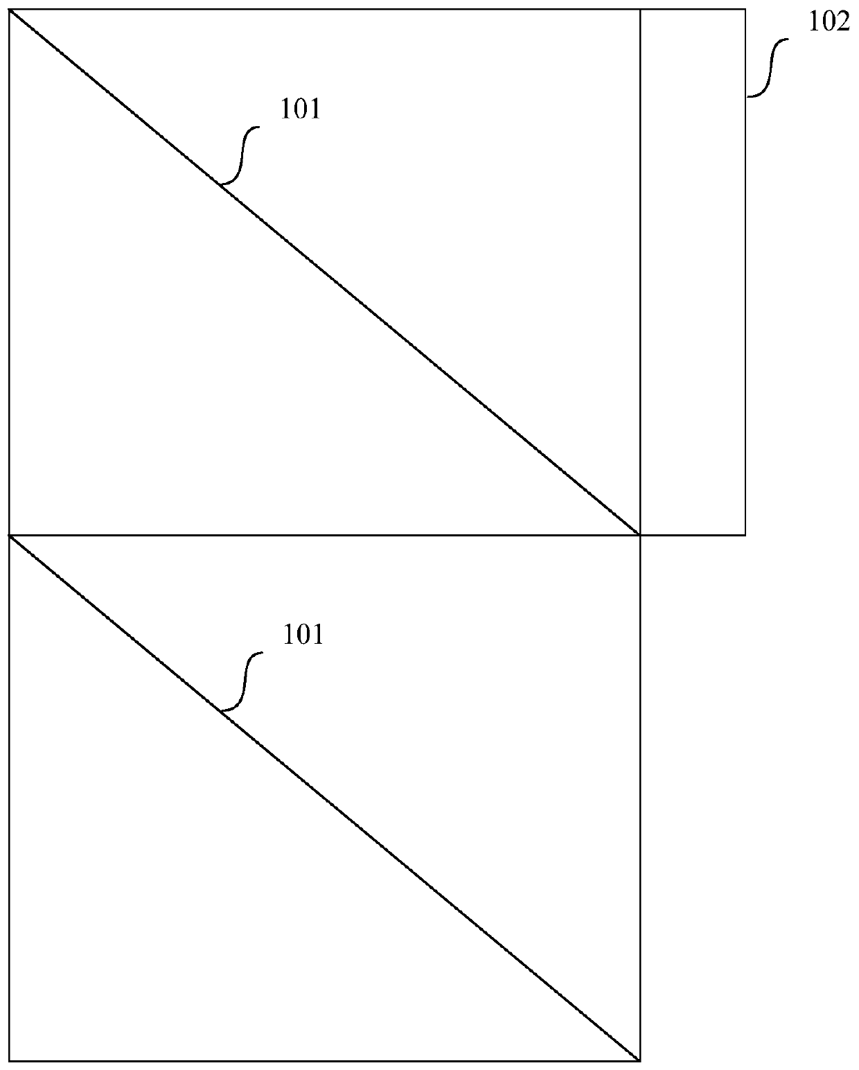
[0014] The polarization conversion device according to the present invention includes a plurality of sub-modules. figure 1 It shows a schematic structural diagram of a sub-module of a polarization conversion device according to an embodiment of the present invention.
[0015] Reference figure 1 , The sub-module includes two polarizing devices and a half retarder. Preferably, the sub-module includes two parts arranged up and down, namely an upper part and a lower part, wherein the upper part and the lower part each include a polarizing device 101, and the half retarder 102 is placed on the upper part.
[0016] Wherein, the half retarder 102 is placed on the upper or lower part. Specifically, if the incident light needs to pass through the sub-module to transmit the first polarized light, the half retarder is superimposed on the lower part; if the incident light needs to pass through the sub-module to transmit the second polarized light, then the half A retarder is superimposed on the upper part.
[0017] Wherein, the polarizing device 101 is used to transmit the first polarized light and reflect the second polarized light. Wherein, the first polarized light and the second polarized light are used to indicate light of a specific polarization state, for example, transmitting S light and reflecting P light, or transmitting P light and reflecting S light.
[0018] Wherein, the polarizing device 101 is placed obliquely and at 45 degrees to the direction of incident light.
[0019] Preferably, the polarizing device 101 is a reflective polarizer.
[0020] Preferably, the polarizing device 101 is a polarized beam splitter (PBS), so as to increase the available beam angle and increase the utilization rate of light energy.
[0021] Preferably, the polarizing device 101 is a line grating.
[0022] Wherein, the half retarder 102 is used to convert the first polarized light transmitted by the polarizing device into the second polarized light.
[0023] Specifically, the one-half phase retarder 102 rotates the vibration direction of linearly polarized light passing through it by 90 degrees.
[0024] Preferably, the half phase retarder is a 102 half wave plate.
[0025] It should be noted that those skilled in the art should be familiar with that a variety of devices can be used to realize the functions of the above-mentioned polarizing device 101 and phase retarder 102, and those skilled in the art can select suitable devices based on actual needs to realize the polarization according to the present invention. Conversion device.
[0026] figure 2 A schematic structural diagram of a polarization conversion device according to an example of the present invention is shown.
[0027] The polarization conversion device according to this example is included in a VR screen, and the number of sub-modules included in the polarization conversion device is more than twice the number of pixels of the VR screen. figure 2 Two sub-modules included in the polarization device of this example, sub-module 201 and sub-module 202 are shown.
[0028] Reference figure 2 , The sub-module 201 and the sub-module 202 each include two parts arranged up and down, an upper part and a lower part. Wherein, the upper part and the lower part each contain a PBS, the PBS is placed obliquely and at 45 degrees to the direction of the incident light, and the half-wave plate is placed on the upper part and attached to the upper part. Among them, PBS is used to transmit P light and reflect S light. The half-wave plate is used to convert the P light transmitted by the PBS into S light.
[0029] Reference figure 2 The arrow shown in to indicate the direction of light. For the sub-module 201, after the unpolarized incident light passes through the PBS on the upper part of the sub-module 201, the P light transmitted by the PBS is then converted into S light after passing through the half-wave plate. The S light reflected by the PBS is After passing the lower PBS, it is reflected by the PBS. After passing through the sub-module 201, the incident light is converted into S light, so that the incident light passes through the sub-module 201 and transmits the S light as a whole. Similarly, the module 202 and the remaining sub-modules included in the polarization conversion device all convert incident light into S light, so that the VR screen emits S light.
[0030] It should be noted that the above examples are only to better illustrate the technical solutions of the present invention, rather than to limit the present invention. Those skilled in the art should understand that any implementation of the polarization conversion device should be included in the scope of the present invention. Inside.
[0031] It should be noted that the above examples are only to better illustrate the technical solutions of the present invention, rather than to limit the present invention. Those skilled in the art should understand that any implementation manner should be included in the scope of the present invention.
[0032] According to the solution of the present invention, incident light is converted into polarized light by a deflection conversion device composed of a plurality of polarizing devices and a half retarder, so that the non-polarized light-emitting screen can be changed to a polarized light-emitting screen, and the The theoretical light energy utilization rate of the optical system is increased to 100%, which greatly improves the light energy utilization rate.
[0033] For those skilled in the art, it is obvious that the present invention is not limited to the details of the foregoing exemplary embodiments, and the present invention can be implemented in other specific forms without departing from the spirit or basic characteristics of the present invention. Therefore, from any point of view, the embodiments should be regarded as exemplary and non-limiting. The scope of the present invention is defined by the appended claims rather than the foregoing description, and therefore it is intended to fall within the claims. All changes within the meaning and scope of the equivalent elements of are included in the present invention. Any reference signs in the claims should not be regarded as limiting the claims involved. In addition, it is obvious that the word "including" does not exclude other units or steps, and the singular does not exclude the plural. Multiple units or devices stated in the system claims can also be implemented by one unit or device through software or hardware. Words such as first and second are used to denote names, but do not denote any specific order.

PUM

no PUM

Description & Claims & Application Information

We can also present the details of the Description, Claims and Application information to help users get a comprehensive understanding of the technical details of the patent, such as background art, summary of invention, brief description of drawings, description of embodiments, and other original content. On the other hand, users can also determine the specific scope of protection of the technology through the list of claims; as well as understand the changes in the life cycle of the technology with the presentation of the patent timeline. Login to view more.

Similar technology patents

Multi-baffle counterflow photo-catalytic reaction device

ActiveCN106512888ALess catalystImprove light energy utilizationChemical/physical/physico-chemical reactor detailsEnergy based chemical/physical/physico-chemical processesEngineeringLight source
Owner:INNER MONGOLIA NORMAL UNIVERSITY

Planting method of annual interplanting and intercropping in mulberry field

InactiveCN106358657AReduce light leakage and loss of reflected lightImprove light energy utilizationClimate change adaptationCultivating equipmentsMutual influenceCrop
Owner:INST OF ECONOMIC CROP HUBEI ACADEMY OF AGRI SCI

Classification and recommendation of technical efficacy words

  • Improve light energy utilization

Spectrum light splitting imaging system light path based on volume hologram grating component light splitting

InactiveCN103134587AImprove light energy utilizationHigh dispersion rate of the systemRadiation pyrometrySpectrometry/spectrophotometry/monochromatorsOptical pathVolume hologram
Owner:BEIJING INSTITUTE OF TECHNOLOGYGY
Why Eureka
Try Eureka