Display device
A technology for display devices and display areas, applied in optics, instruments, sensors, etc., can solve problems affecting the sound quality of speakers and easily disturbing liquid crystal molecules
- Summary
- Abstract
- Description
- Claims
- Application Information
AI Technical Summary
Problems solved by technology
Method used
Image

Examples
no. 1 example
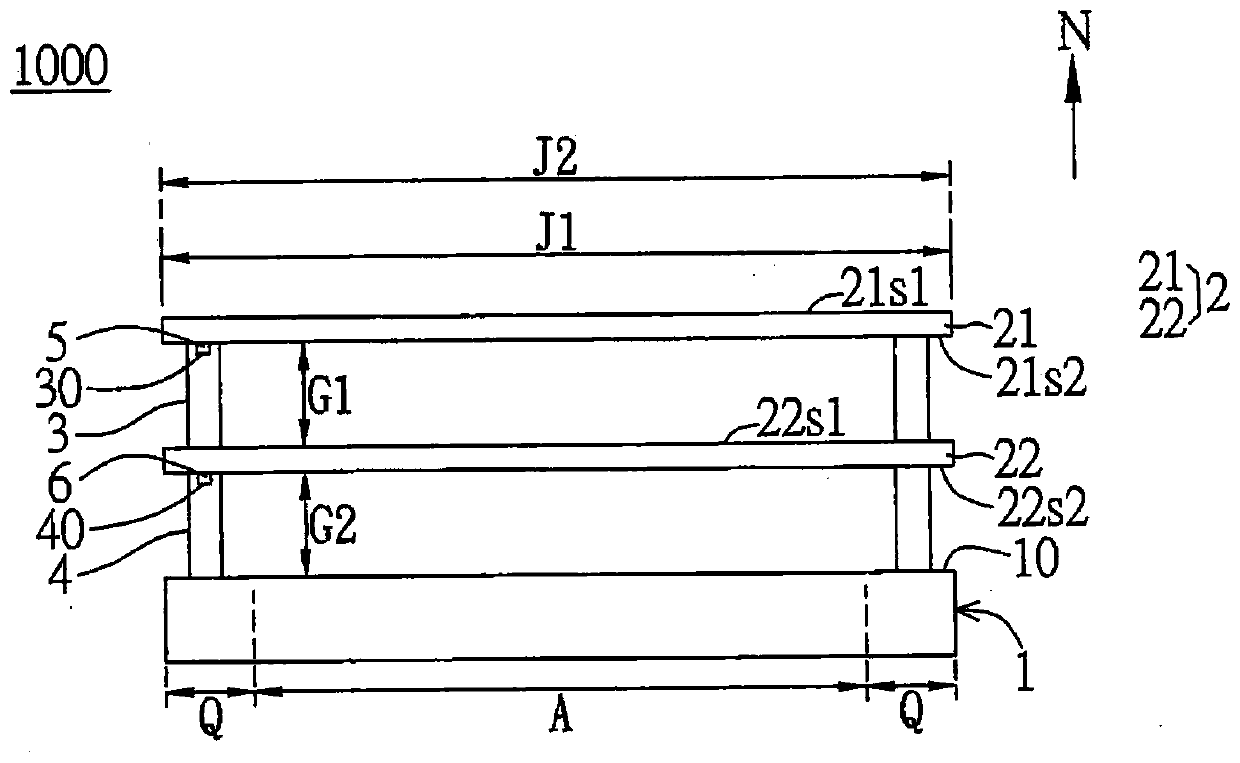
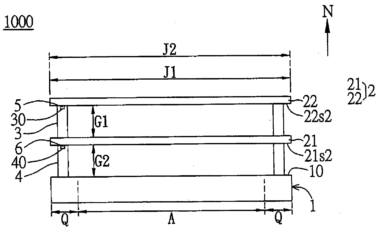
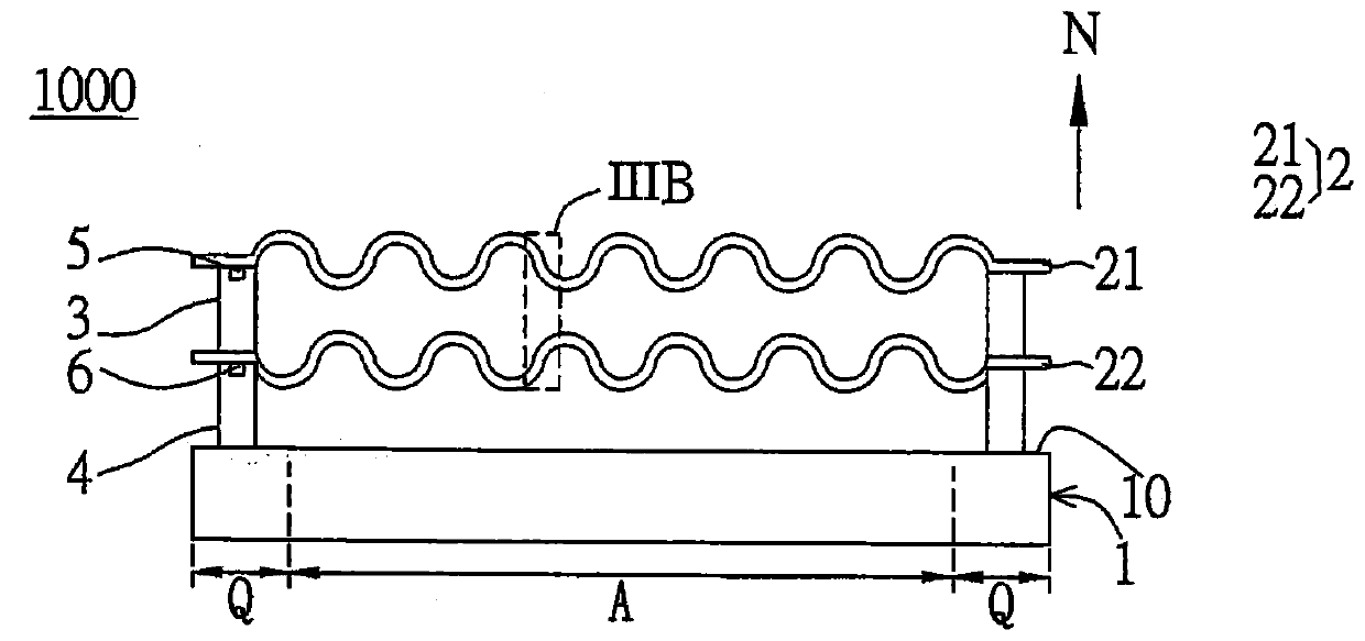
[0098] The following will match Figure 1 to Figure 8 A display device according to a first embodiment of the present invention will be described. see figure 1 , the first embodiment of the present invention provides a display device 1000 including a display panel 1 and a speaker module 2 . The speaker module 2 is disposed on the light emitting surface 10 of the display panel 1 and has a sound emitting film 21 and an image compensation film 22 . The sound-emitting film 21 and the image compensation film 22 are arranged along the normal direction N of the light-emitting surface 10 , so the light emitted from the light-emitting surface 10 as an image display passes through the sound-emitting film 21 and the image compensation film 22 and then exits outward. To be specific, in this embodiment, the image compensation film 22 is disposed between the display panel 1 and the sound emitting film 21, such as figure 1 shown; however, the present invention is not limited thereto. In ...
no. 2 example
[0114] see Figure 11 , Figure 11 It is an exploded schematic view of the display device 2000 according to the second embodiment of the present invention. The main difference between this embodiment and the first embodiment is that the first embodiment respectively uses the first actuating element 5 and the second actuating element 6 to actuate the sound emitting film 21 and the image compensation film 22 as a whole, so as to generate anti-phase The first vibration wave and the second vibration wave; in this embodiment, the sound-generating membrane 21 is still disposed on one side of the light-emitting surface 10 of the display panel 1 , but is configured to be actuated by divisions.
[0115] For details, please refer to Figure 11 . In this embodiment, the display panel 1 includes a plurality of pixel regions P and light-shielding regions B between the pixel regions P. As shown in FIG. Figure 11 In the embodiment, the pixel area P refers to the area where each sub-pixe...
no. 3 example
[0119] see Figure 13 , which shows a display device 3000 according to the third embodiment of the present invention. The main difference between this embodiment and the first embodiment is that the display device 3000 of this embodiment utilizes the principle of differential pressure actuation to make the acoustic film 21 and the image compensation film 22 emit vibratory sound waves in opposite phases.
[0120] In detail, in this embodiment, the acoustic film 21 and the image compensation film 22 are preferably made of electret material, and the display device 3000 has a first electrode group 91 and a second electrode group 92, wherein the first electrode group 91 Including at least one first electrode layer, the second electrode group 92 includes at least one second electrode layer. For example, Figure 13 In the embodiment, the first electrode group 91 has two first electrode layers 911, 912, which are respectively arranged on the upper surface 21s1 and the lower surface ...
PUM
 Abstract
Description
Claims
Application Information