Detachable tool rest on numerically-controlled machine tool

A CNC machine tool and detachable technology, applied in the field of machinery, can solve problems such as time and energy spent on operators, reduced production efficiency of enterprises, bending deformation of tools, etc., so as to achieve unaffected machining accuracy, fast replacement speed, and tool change efficiency. high effect

Active Publication Date: 2014-07-16
海德曼(上海)自动化技术有限公司
View PDF9 Cites 3 Cited by
  • Summary
  • Abstract
  • Description
  • Claims
  • Application Information

AI Technical Summary

Problems solved by technology

The number of tool holders on the turret is limited, and sometimes it cannot meet all the procedures required for the processing of a certain workpiece, or when the tool is damaged, the tool needs to be replaced. According to the structure of the existing CNC machine tool, the general method is , first stop the CNC machine tool, then remove the tool installed in the tool holder on the turret of the CNC machine tool and replace it with a new tool, and then restart the CNC machine tool
[0003] However, there are some deficiencies in this tool changing method of traditional CNC machine tools: First, as we all know, if the tool is processed without tool setting, it is prone to bending deformation or even tool breakage. Therefore, in order to ensure the cutting The accuracy of the tool and the stability of the tool are guaranteed. After the tool is replaced, the tool needs to be re-set in the CNC machine tool. However, the CNC machine tool needs to be kept in the shutdown state during the tool-setting process, which not only takes a lot of time, but also reduces The production efficiency of the enterprise is improved; in addition, the tool holder and the base fixed on the turret are fixedly connected to each other and cannot be disassembled. Therefore, when changing the tool, the tool can only be removed from the tool holder, and then replaced with a new tool. It also takes a lot of time and energy for the operator during the tool change process, and the tool change process is also relatively complicated. In addition, because the tool holder cannot be disassembled, the tool after each tool change needs to be aligned in the CNC machine tool. Therefore, there are also problems such as poor reset accuracy and unreliable positioning.

Method used


Image

  • Detachable tool rest on numerically-controlled machine tool
  • Detachable tool rest on numerically-controlled machine tool
  • Detachable tool rest on numerically-controlled machine tool

Examples


Embodiment 1

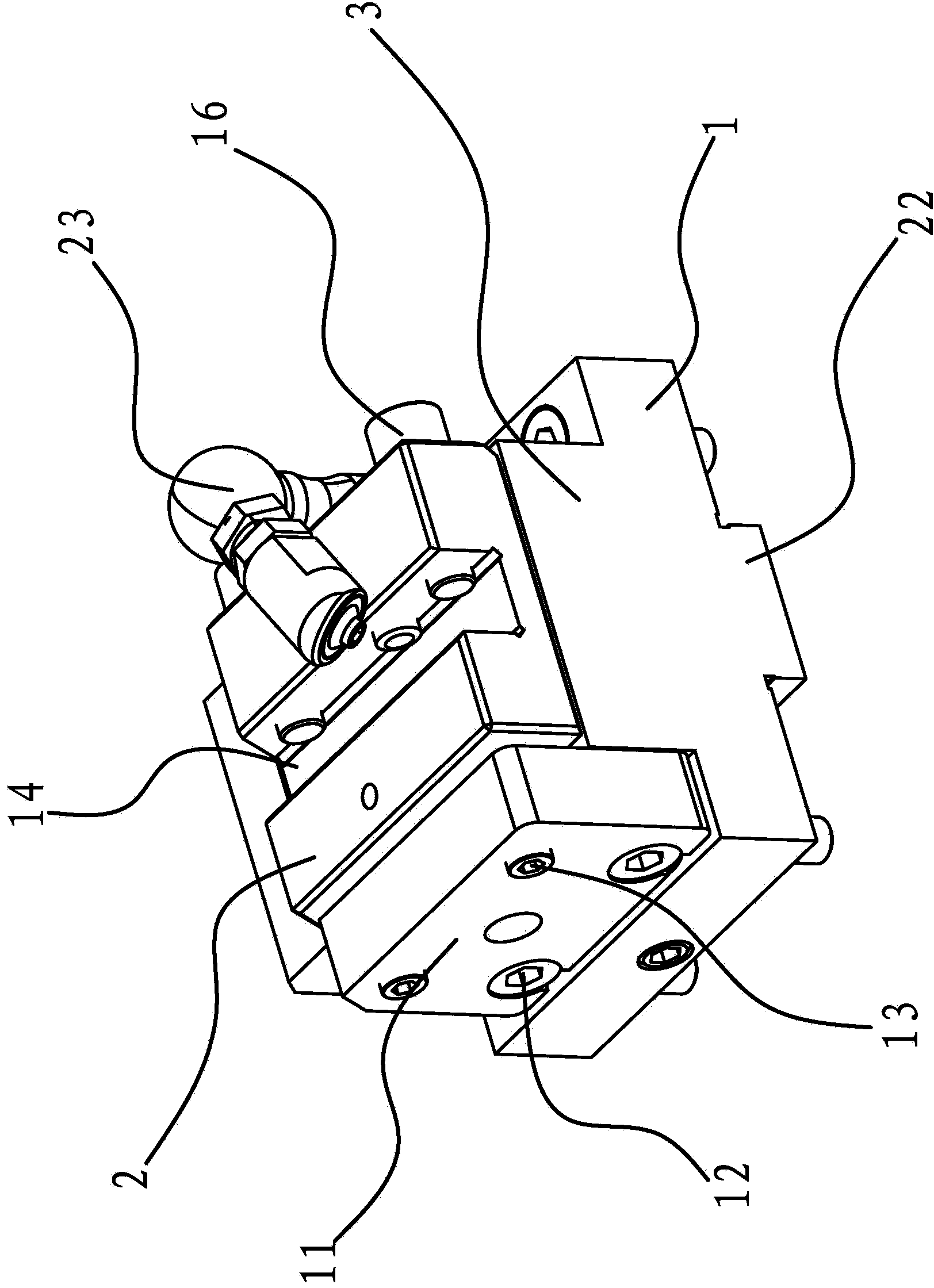
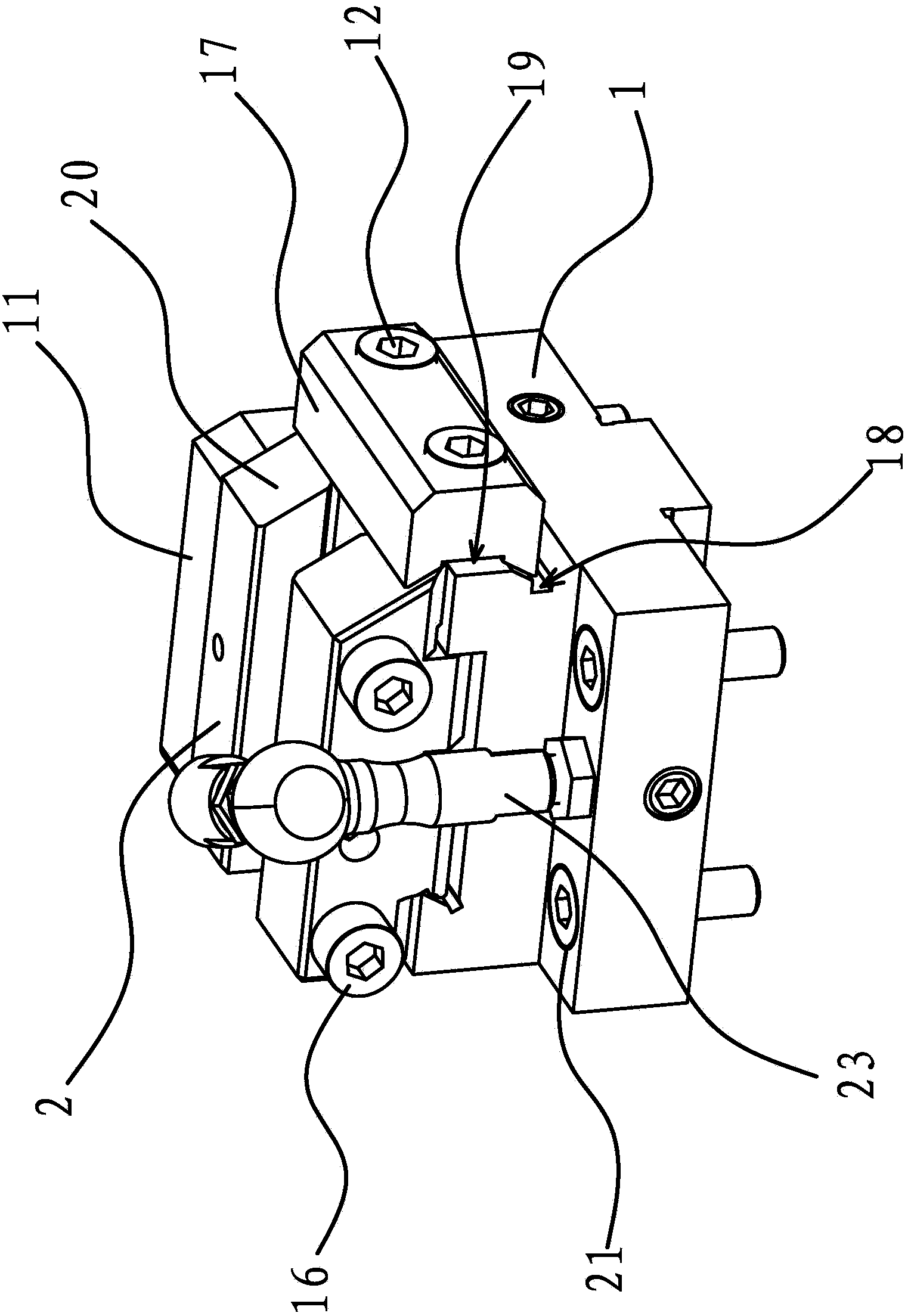
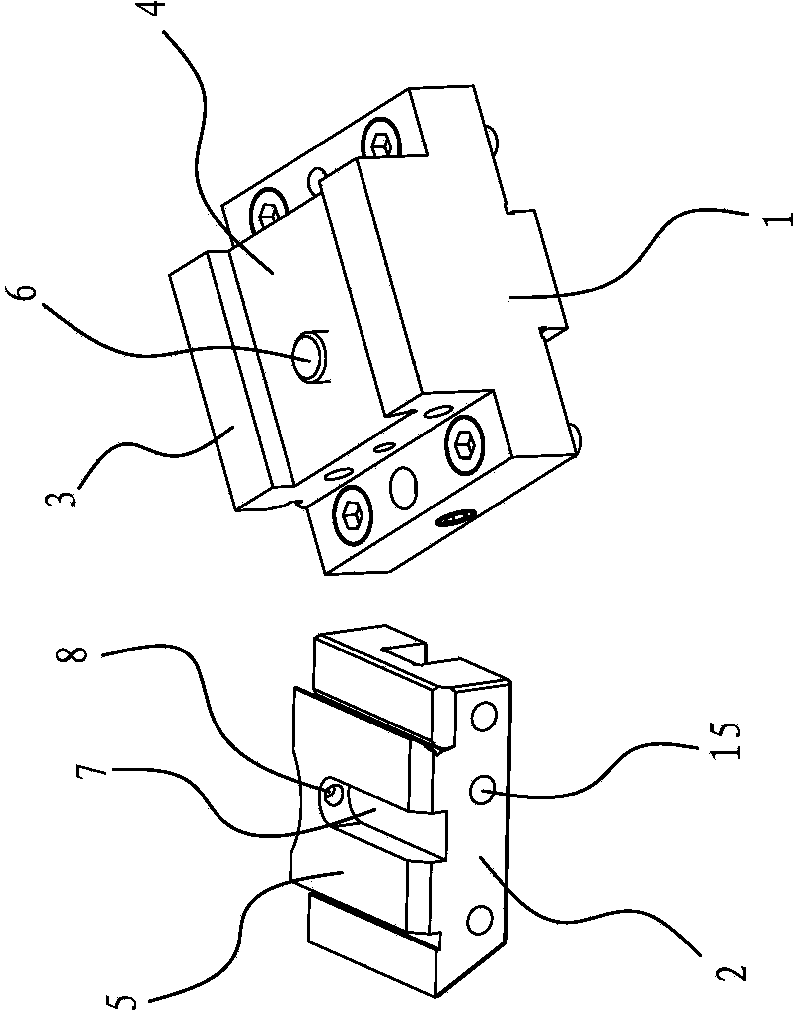
[0038] Such as Figure 1-Figure 6 As shown, a detachable tool rest used on a CNC machine tool, the CNC machine tool has a turret, the detachable tool rest includes a base 1 for fixing on the turret and a tool rest connected to the base 1 The main body 2 and the base 1 have a positioning boss 3 , and the positioning boss 3 is provided with a slot 4 passing through its side, and the base 1 of the tool holder body 2 has a snap-in portion 5 that can be snapped into the slot 4 .

[0039] Such as figure 1 As shown, the side of the positioning boss 3 perpendicular to the card slot 4 is fixedly connected with the baffle 11 through the fastening screws 12, and the side of the baffle 11 is pressed against the side of the tool holder body 2 by several fastening studs 13 . The knife rest body 2 is block-shaped, and the surface of the knife rest body 2 is provided with a tool mounting groove 14, and the other side where the knife rest body 2 is connected with the baffle plate 11 has seve...

Embodiment 2

[0050] The structure and principle of this embodiment are basically the same as that of Embodiment 1, the difference is that the blocking member in this embodiment includes a bar that protrudes upwards from the bottom of one end of the slot 4, and the corresponding end of the engaging part 5 has a When the tool rest body 2 is clipped onto the base 1 until the notch on it abuts against the bar at the bottom of the slot 4, the tool post body 2 is clipped to the specified position on the base 1.

Embodiment 3

[0052] The structure and principle of this embodiment are basically the same as that of Embodiment 1, the difference is that: there are several connecting holes 1 distributed on the surface of the knife holder body 2 in this embodiment, and a number of connecting holes 2 are correspondingly distributed on the base 1, and the fixing parts include Pass through the connecting hole one and pass through the latch in the connecting hole two. After the tool holder body 2 is clamped with the base 1 , the bolt is used to pass through the connection hole and penetrate into the connection hole 2, so that the tool holder body 2 and the base 1 are fixed.


PUM


Abstract

The invention provides a detachable tool rest on a numerically-controlled machine tool, and belongs to the technical field of machines. The detachable tool rest on the numerically-controlled machine tool solves the problems that according to an existing numerically-controlled machine tool, replacement efficiency of a tool is low, and operation is complex in the replacement process. The detachable tool rest on the numerically-controlled machine tool comprises a base and a tool rest body connected to the base and used for fixing a tool, wherein the base is provided with a positioning boss, the surface of the positioning boss is provided with a clamping groove which penetrates through the side portion of the positioning boss, and the bottom of the tool rest body can be clamped into a clamping part in the clamping groove; a stopping piece and a fixing piece are arranged between the tool rest body and the base, the stopping piece enables the tool rest body to be clamped at a specific position, and the tool rest body and the base can be fixed by the fixing piece after being clamped at the specific position. The detachable tool rest on the numerically-controlled machine tool has the advantages that tool replacement efficiency is high, the tool replacement speed is high, and in-machine tool setting is not needed after tool replacement.

Description

technical field [0001] The invention belongs to the technical field of machinery, and relates to a tool holder for a numerically controlled machine tool, in particular to a detachable tool holder for a numerically controlled machine tool. Background technique [0002] In order to facilitate the processing of the workpiece and ensure the processing efficiency of the workpiece, the traditional CNC machine tool is equipped with a turret. There are a number of bases on the turret, and a tool holder is fixed on the base. Each tool holder is equipped with a corresponding Tool, during the machining process, the tool required for the current machining can be selected through the rotation of the turret. The number of tool holders on the turret is limited, and sometimes it cannot meet all the processes required for the processing of a certain workpiece, or when the tool is damaged, the tool needs to be replaced. According to the structure of the existing CNC machine tool, the general ...

Claims


Application Information

Patent Timeline
Patent Type & Authority Applications(China)
IPC IPC(8): B23B21/00
CPCB23Q1/70
Inventor 葛建伟石鑫韩照
Owner 海德曼(上海)自动化技术有限公司
Why Eureka
Try Eureka