
Supporting protection device for permanent magnet synchronous motor and mounting method thereof

A permanent magnet synchronous motor and protection device technology, which is applied in the direction of electromechanical devices, casings/covers/supports, electrical components, etc., can solve problems such as high maintenance costs and affect the surface heat dissipation performance of permanent magnet synchronous motors, and achieve indirect Positioning installation, ensuring the stability of the overall structure, and facilitating snap-in installation

Active Publication Date: 2019-05-21
浙江晋一特种电机有限公司
View PDF5 Cites 2 Cited by
  • Summary
  • Abstract
  • Description
  • Claims
  • Application Information

AI Technical Summary

Problems solved by technology

In the prior art, during the actual installation process of the permanent magnet synchronous motor, the surface is generally protected by a simple protective cover. Although the protective cover can play a protective role, it affects the heat dissipation performance of the permanent magnet synchronous motor surface
Moreover, the existing protective cover is generally integrally formed. Although the installation process is simple, once a problem occurs in the actual use of the protective cover, the entire protective cover must be completely replaced, resulting in high subsequent maintenance costs.

Method used


Image

  • Supporting protection device for permanent magnet synchronous motor and mounting method thereof
  • Supporting protection device for permanent magnet synchronous motor and mounting method thereof
  • Supporting protection device for permanent magnet synchronous motor and mounting method thereof

Examples


Embodiment Construction

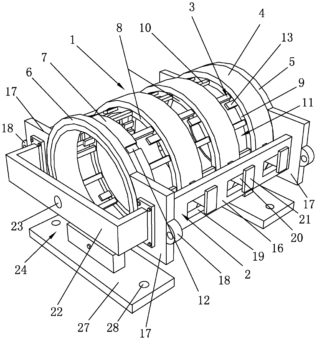
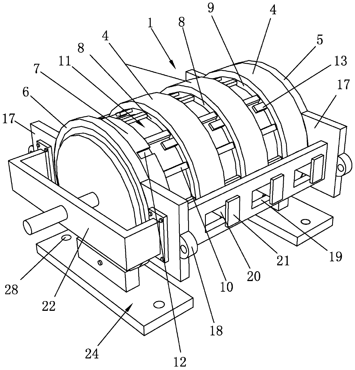
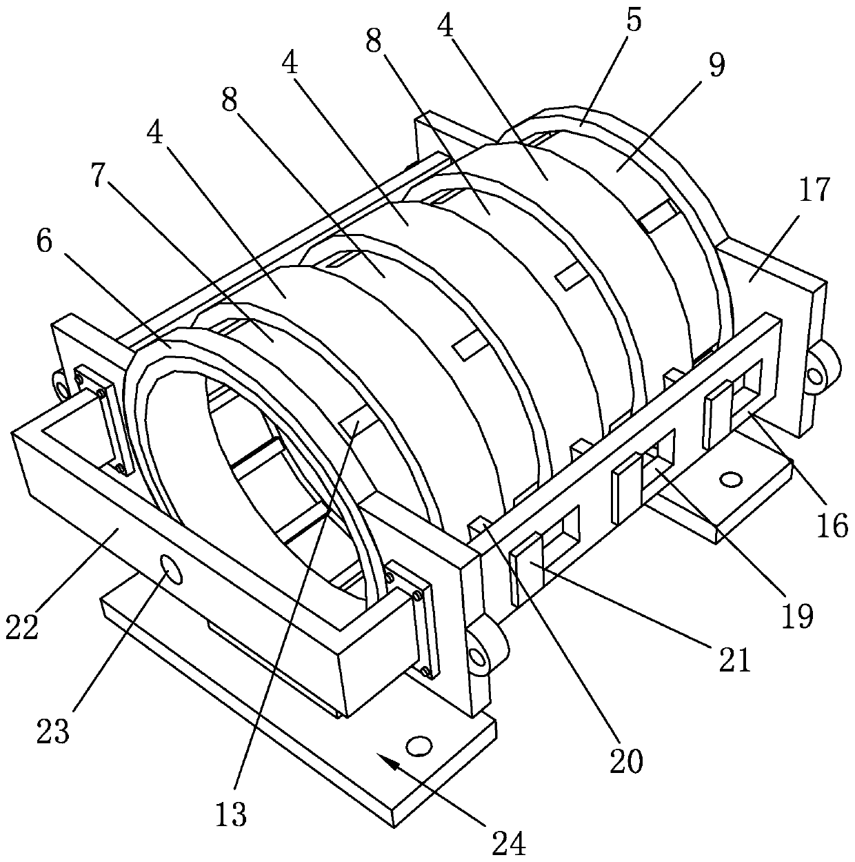
[0042] Such as Figure 1 to Figure 9 As shown, it is a support and protection device for a permanent magnet synchronous motor according to the present invention, which includes a protective cover 1 and an auxiliary frame 2. The protective cover 1 includes a base shell 3 and a shielding ring 4. The right end of the base shell 3 is provided with a seal Baffle plate 5, collar 6 is arranged on the outer peripheral surface of the left end of base shell 3, base shell 3 comprises left end ring 7, middle ring 8 and right end ring 9, the width of left end ring 7, middle ring 8 and right end ring 9 , the radius of the outer circumference and the radius of the inner circumference are all matched, so that the middle ring 8 and the right end ring 9 are suitable for the shielding ring 4 of the same size, which is convenient for actual processing and forming, and the left end ring 7, the middle ring 8 and the right end ring 9 The radius of the inner circumference matches the radius of the ou...


PUM


Abstract

The invention discloses a supporting protection device for a permanent magnet synchronous motor. The supporting protection device comprises a protective cover and an auxiliary rack, wherein the protective cover comprises a basic shell and blocking rings; the basic shell comprises a left end ring, middle rings and a right end ring; the middle rings are uniformly arranged between the left end ring and the right end ring; and the blocking rings are arranged on the middle rings and the right end ring in a sleeving manner. The mounting method comprises the following steps: 1), mounting the protective cover; 2), mounting a support base; 3), mounting the auxiliary rack; and 4), mounting the supporting protection device and the permanent magnet synchronous motor. According to the supporting protection device disclosed by the invention, blocking protection of the permanent magnet synchronous motor can be realized, and indirect mounting positioning between the permanent magnet synchronous motorand the equipment is also realized, so that mechanical vibration and noise of the permanent magnet synchronous motor in practical use can be effectively reduced, and meanwhile, a mode of the protective cover of the supporting protection device can be changed according to different use environments and places of the permanent magnet synchronous motor, and thus, the permanent magnet synchronous motor can be applied to multiple different using environments.

Description

technical field [0001] The invention belongs to the technical field of permanent magnet synchronous motors, and in particular relates to a support protection device for permanent magnet synchronous motors and an installation method thereof. Background technique [0002] The permanent magnet synchronous motor is a synchronous motor that is excited by a permanent magnet to generate a synchronous rotating magnetic field. The permanent magnet acts as a rotor to generate a rotating magnetic field. The three-phase stator winding reacts through the armature under the action of the rotating magnetic field to induce a three-phase symmetrical current. At this time, the kinetic energy of the rotor is converted into electric energy, and the permanent magnet synchronous motor is used as a generator; in addition, when the three-phase symmetrical current is passed into the stator side, since the three-phase stators have a difference of 120 in space, the three-phase stator currents rotate in...

Claims


Application Information

Patent Timeline
IPC IPC(8): H02K5/04H02K5/00H02K5/24H02K5/20H02K5/10
Inventor 周锦法
Owner 浙江晋一特种电机有限公司
Learn More