Method capable of keeping and observing cupping temperature and cupping device
A technology of thermal insulation cavity and tank body, which is applied in glass suction cups, physical therapy and other directions to achieve the effects of increasing medical effects, convenient use and low price
- Summary
- Abstract
- Description
- Claims
- Application Information
AI Technical Summary
Problems solved by technology
Method used
Image

Examples
Embodiment Construction
[0046] The present invention will be described below in conjunction with the first specific embodiment.
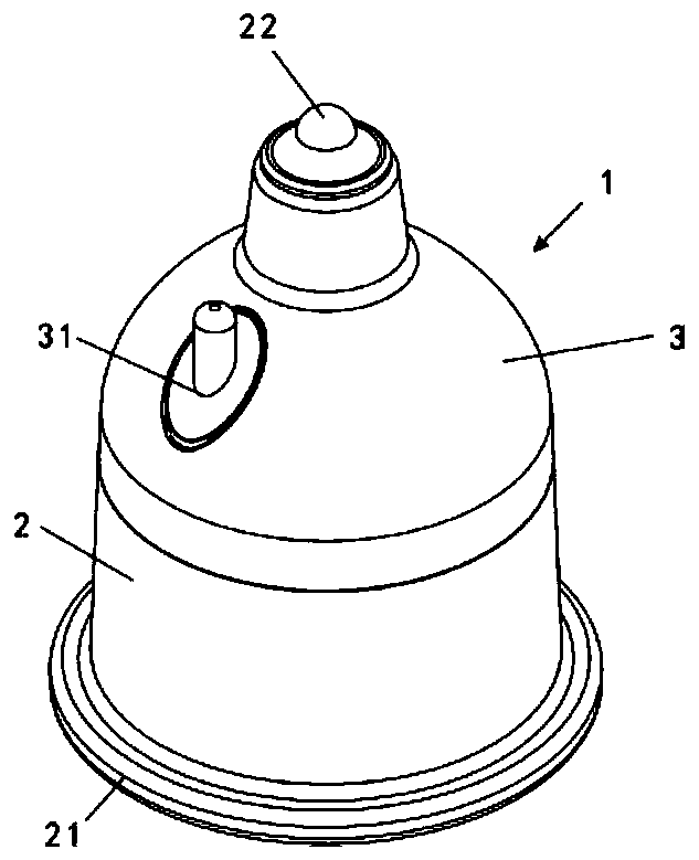
[0047] Such as Figure 1 to Figure 5 As shown, the best embodiment for implementing the method that can maintain the cupping temperature includes:
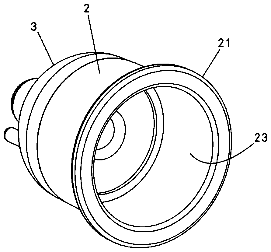
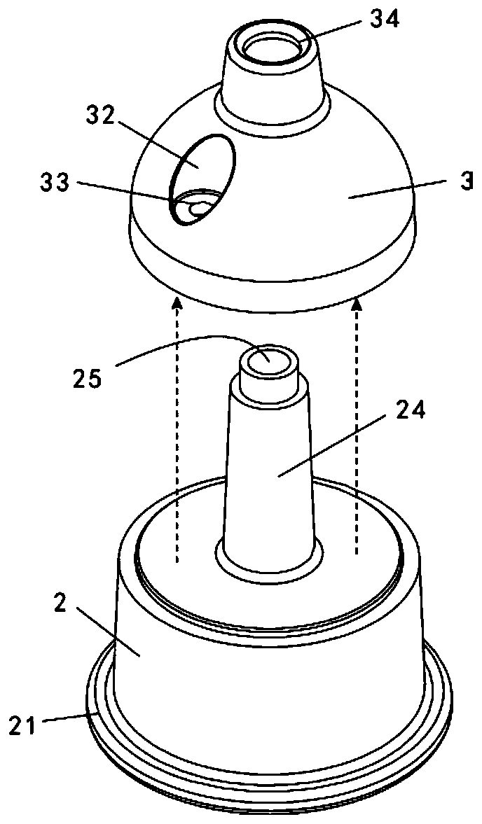
[0048] The first step, a cupping main tank body 2 is set, and the cupping main tank body 2 has an upward vent pipe 24, and a heat preservation liquid chamber 3 is arranged around the vent pipe 24, and the heat preservation liquid chamber 3 is filled with heat preservation liquid;
[0049] In the second step, a main tank plug 22 is set at the port where the vent pipe 24 extends to the end of the heat preservation liquid chamber 3;
[0050] The 3rd step, on the housing of the heat preservation liquid chamber 3, the heat preservation cavity plug seat 32 is set, the heat preservation cavity body plug seat hole 33 is set on the heat preservation cavity body plug seat 32, and the hole is connected to the heat preservation cavity; ...
PUM
 Abstract
Description
Claims
Application Information
PatSnap Eureka turns technology decisions into work you can execute. Powered by our Innovation Knowledge Graph, it runs expert workflows across engineering, life sciences, materials and intellectual property. Get your review-ready output in minutes.


