

Automatic loading and unloading robot for part machining
A technology of automatic loading and unloading and parts processing, applied in the field of robotics, can solve the problems of inaccurate and suitable positions, single working ability of robots, and low degree of automation of robots, and achieve smooth adjustment and movement before and after, saving time and effort in use, and ensuring universality Effect
- Summary
- Abstract
- Description
- Claims
- Application Information
AI Technical Summary
Problems solved by technology
Method used
Image

Examples
Embodiment Construction
[0046] The technical solutions of the present invention will be clearly and completely described below in conjunction with the embodiments. Apparently, the described embodiments are only some of the embodiments of the present invention, not all of them. Based on the embodiments of the present invention, all other embodiments obtained by persons of ordinary skill in the art without creative efforts fall within the protection scope of the present invention.
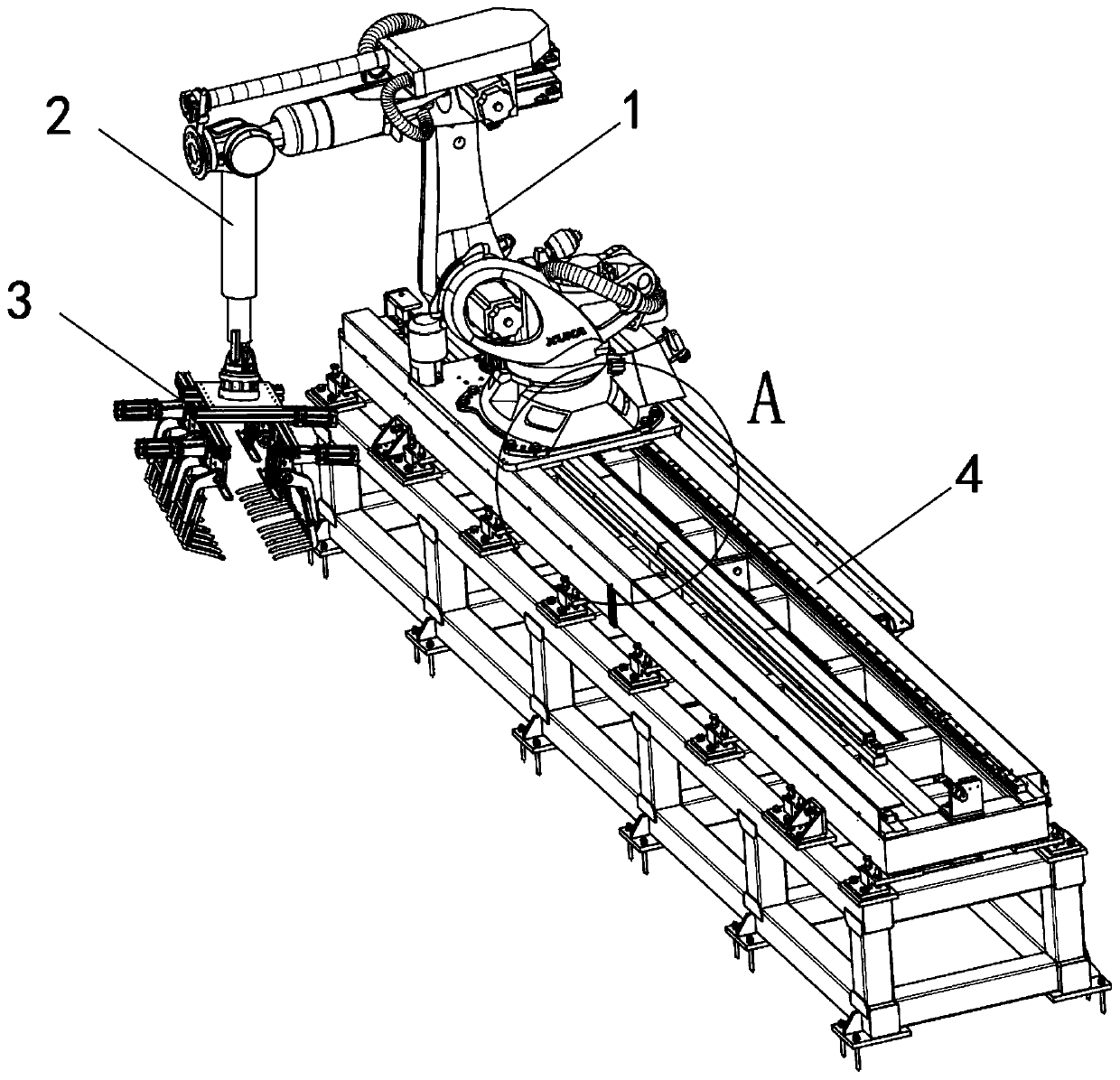
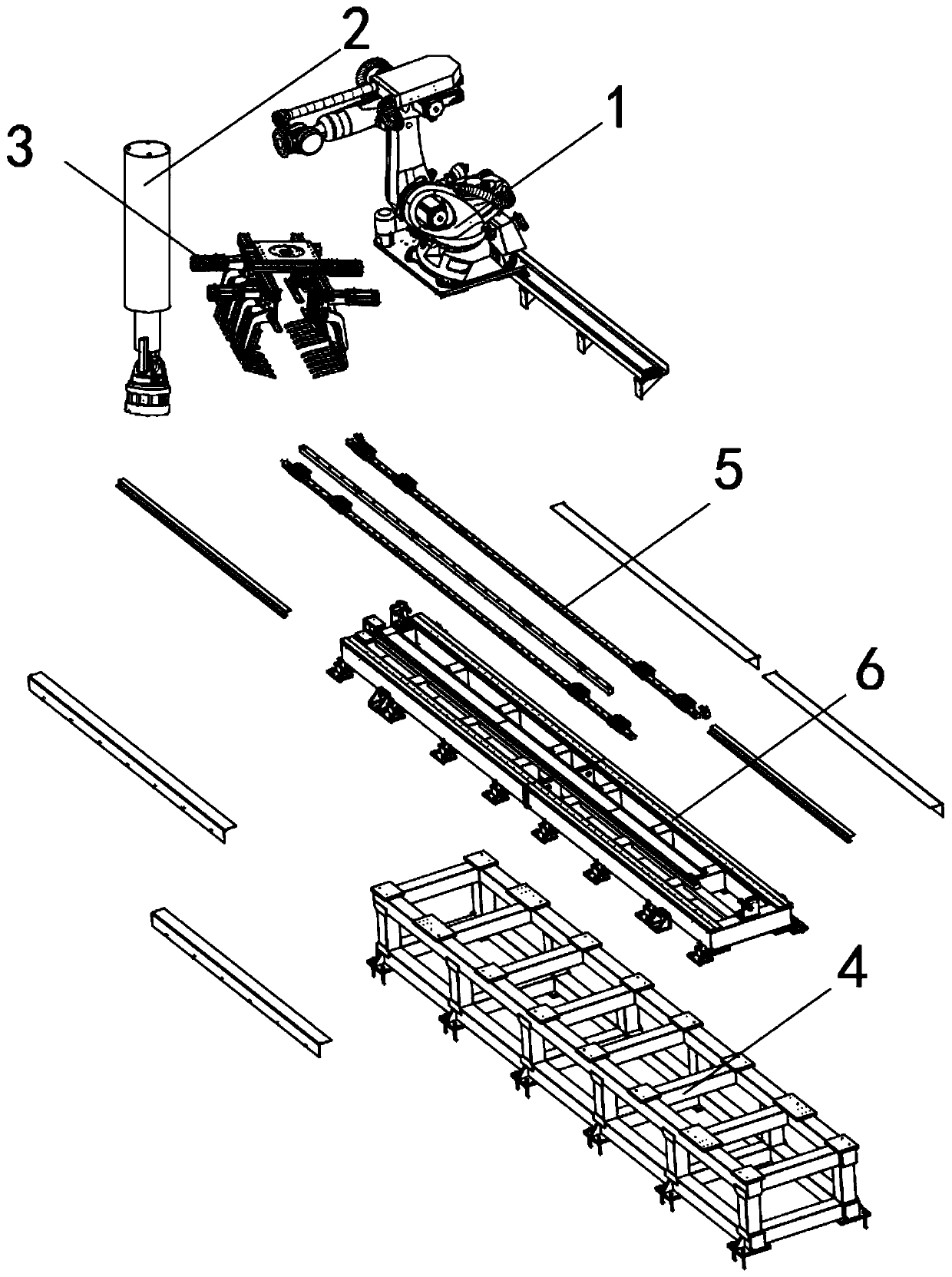
[0047] see Figure 1-14 As shown, an automatic loading and unloading robot for parts processing, including a transfer frame 1, a hydraulic pump 2, a material grabbing tray 3 and a machine base 4, and an organic base 4 is arranged under the transfer frame 1;
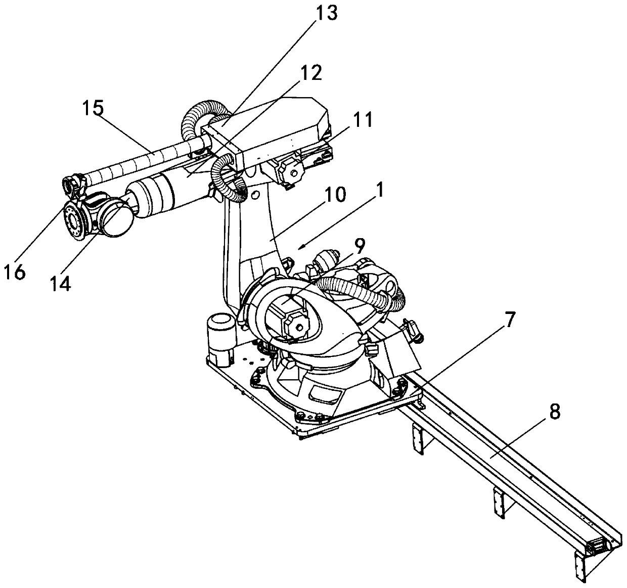
[0048] The bottom of the transposer 1 is horizontally provided with a mobile platform 7, and one end of the mobile platform 7 is provided with a motor one 8, the top of the mobile platform 7 is provided with a motor four 20, and the top of the motor four 20 is rotated ...
PUM
 Abstract
Description
Claims
Application Information